What "negative resistance" means
In linear circuits, resistance always absorbs real power.
But the diode plug is nonlinear and time‑variant, so there are intervals where it returns energy to the AC source.
When analyzing only the fundamental AC component, this can appear as:
\(
G = \frac{P_1}{|V_1|^2} < 0
\)
A negative conductance \(G\) corresponds to an apparent negative resistance.
This does not violate energy conservation — it is a measurement artifact of nonlinear energy flow.
Why the diode plug behaves this way
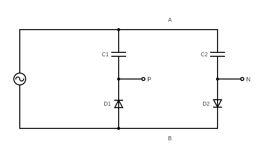
The diode plug uses two rectifying branches feeding two capacitors.
Because the diodes conduct only during specific parts of the AC cycle:
- Charging intervals: energy flows from the AC node into the capacitors → positive instantaneous power
- Discharging intervals: energy flows from the capacitors back into the AC node → negative instantaneous power
When averaged and reduced to the fundamental, the returned energy can exceed the absorbed energy at that frequency, producing an effective negative real power.
The diode plug strongly distorts the AC waveform:
- clips parts of the cycle
- injects harmonics
- shifts current relative to voltage
Because the fundamental component is only a slice of the total waveform, it can show a net negative real power, even though the total instantaneous power is always non‑negative.
Thus the device can appear to behave like a source at the fundamental frequency.
The capacitors charge in short pulses rather than smoothly. This pulsed charging makes the device appear more capacitive than a simple capacitor.
The imaginary part of the admittance:
\(
B = \frac{Q_1}{|V_1|^2}
\)
often becomes negative, indicating capacitive behavior.
Increasing capacitance increases:
- waveform distortion
- reactive power
- the magnitude of the apparent negative resistance
---
How the negative resistance is measured:
Voltage and current at the AC node are sampled and transformed via FFT.
The fundamental components give:
\(
Y_{eq} = \frac{I_1}{V_1} = G + jB
\)
Where:
- \(G < 0\) → apparent negative resistance
- \(B < 0\) → capacitive behavior
This linearized model describes how the diode plug interacts with a resonant tank or AC source at the fundamental frequency.
---
The diode plug does not generate energy.
It redistributes energy between harmonics and between the AC node and its capacitors.
When viewed only at the fundamental frequency, this redistribution can look like:
- negative resistance (returning real power)
- negative susceptance (strong capacitive effect)
But the total energy always obeys conservation laws!