Hello, so I want to share with you my experiments with PEG cell.
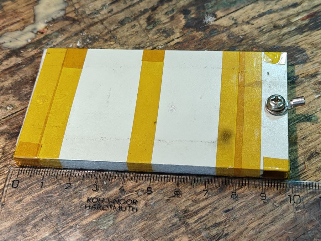
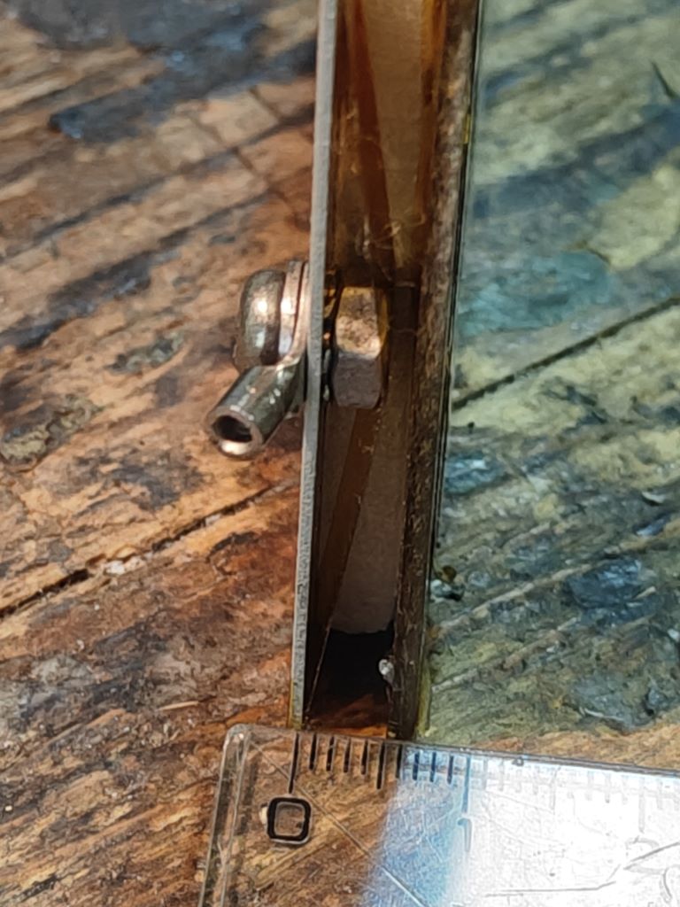
My current main cell.
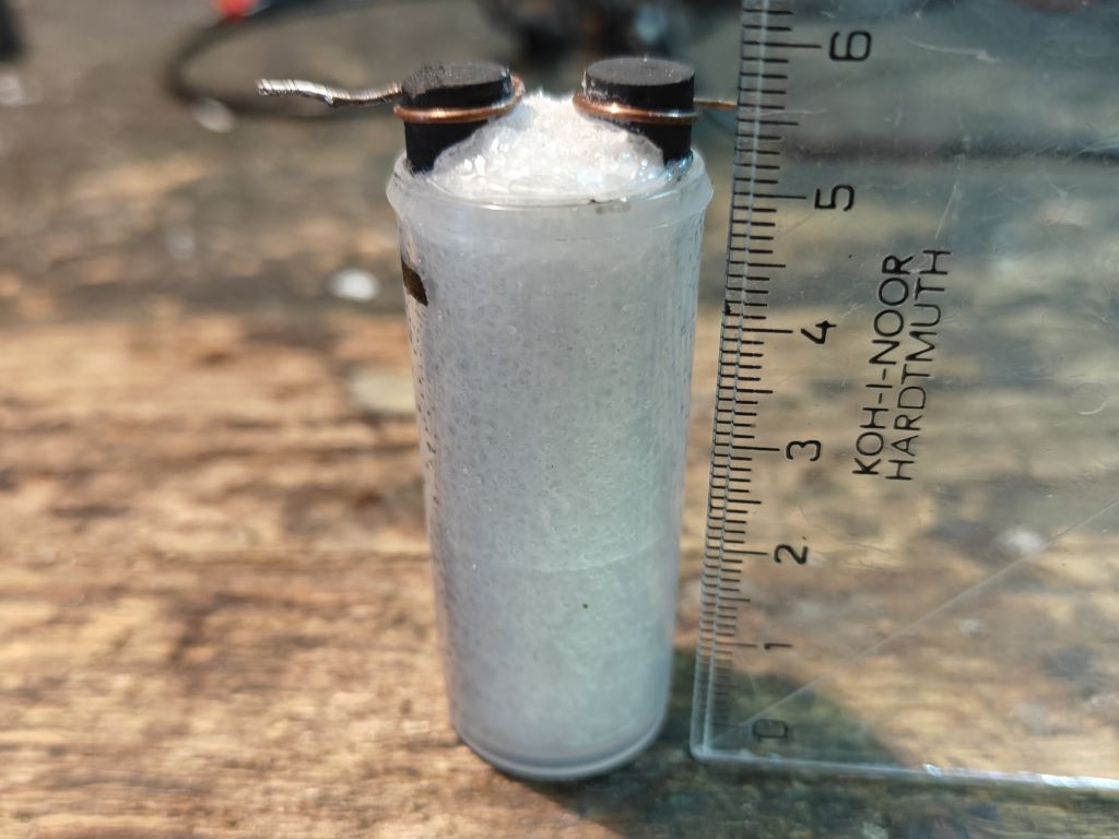
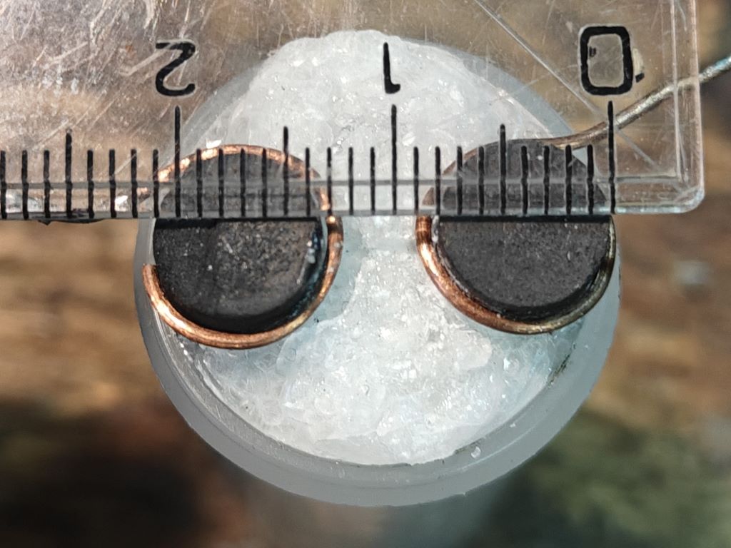
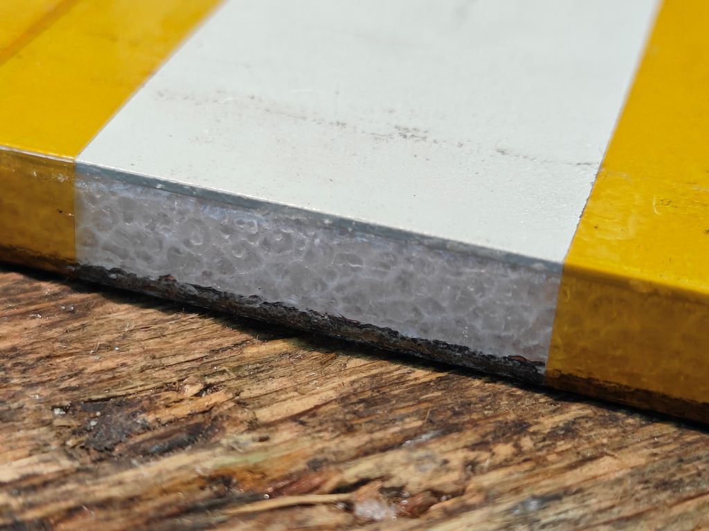
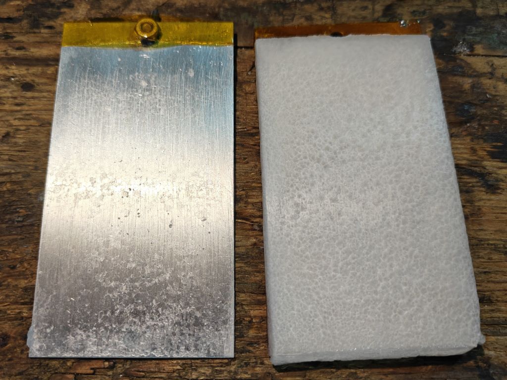
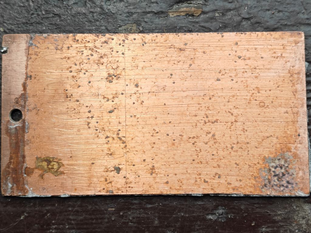
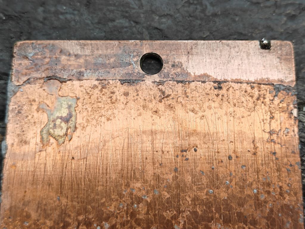
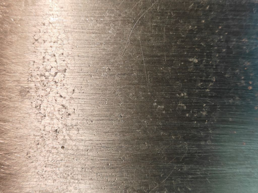
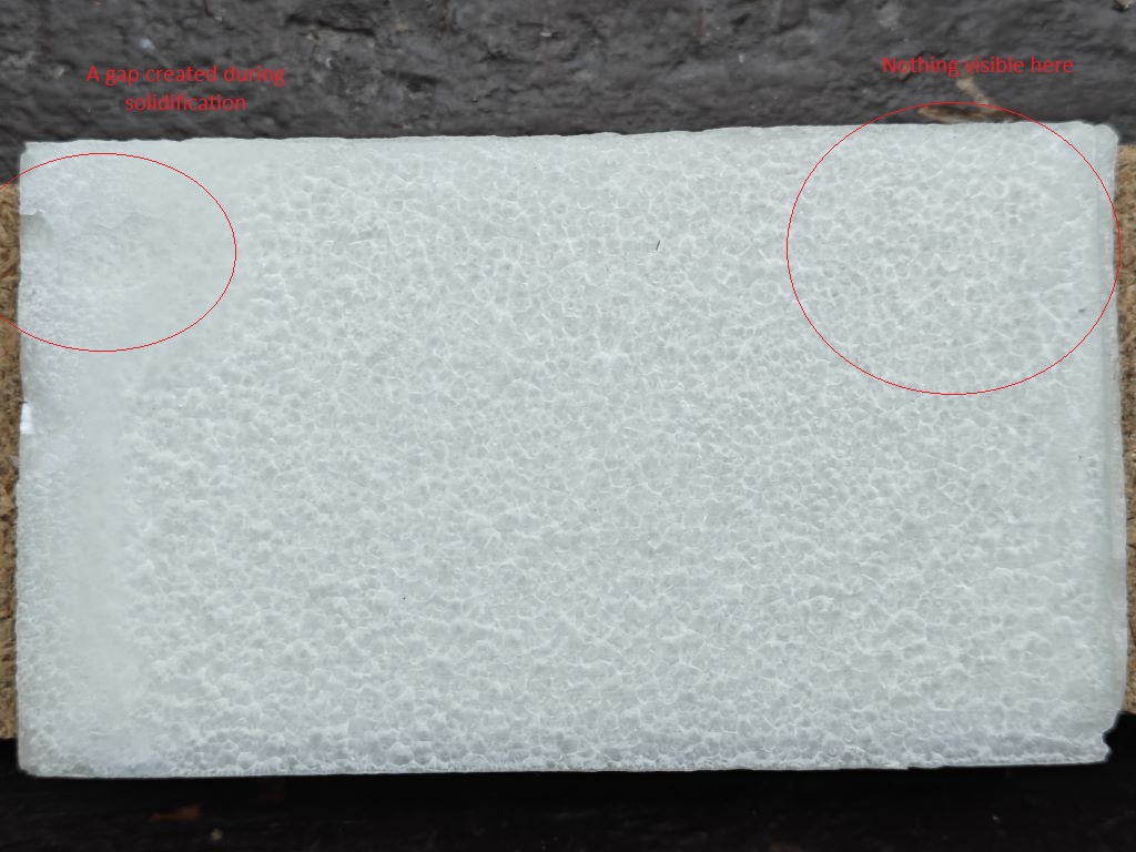
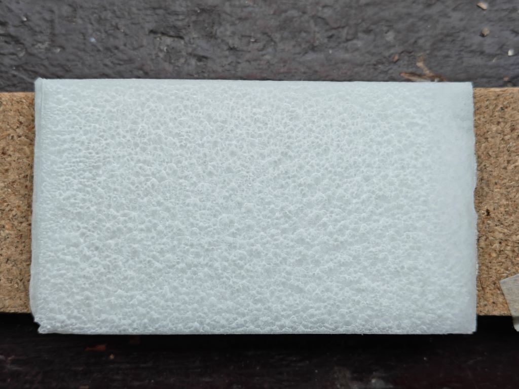
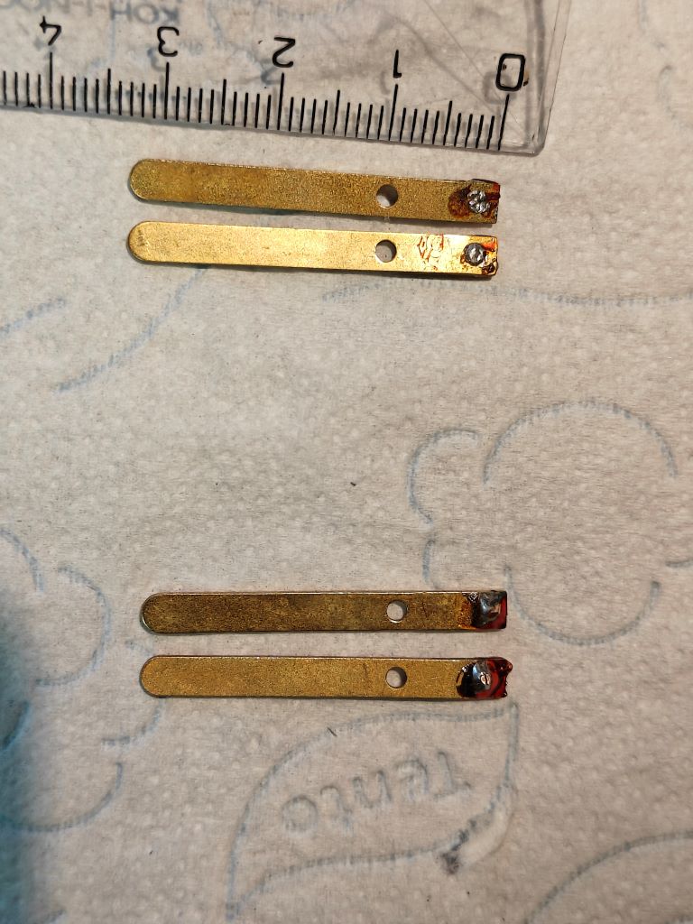
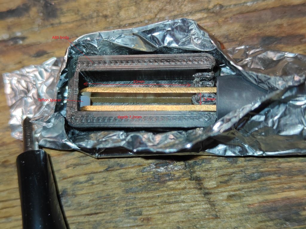
Construction -Electrodes are burnt and properly cleaned carbon rods from A batteries (ordinary large Zn/C cells). Electrolyte pure PEG8000. I covered the electrodes with melted PEG. I previously let the molten PEG stand in an open container for about 20 minutes at about 90°C (194°F) to evaporate some moisture, but it certainly wasn't enough to dry completely. But I honestly have no idea how much moisture is in it. When PEG cools it shrinks. To prevent cavities from forming, I added melted PEG several times during cooling.
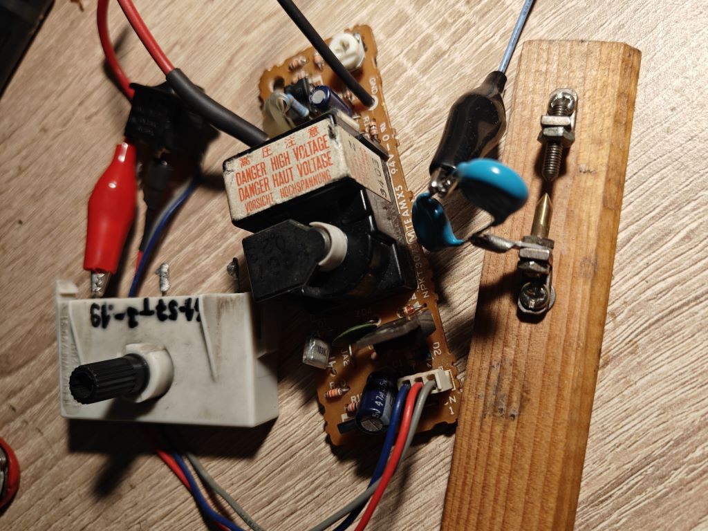
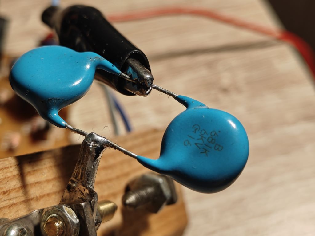
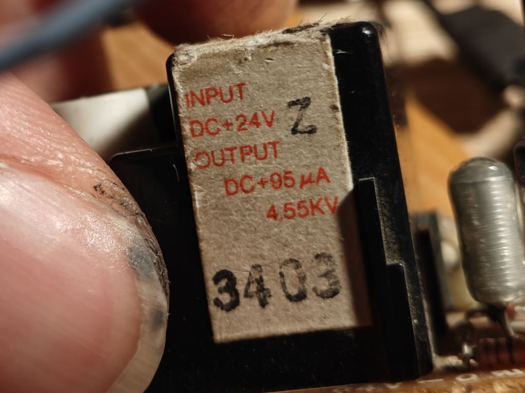
From pouring to complete solidification, I applied high voltage pulses to the electrodes. The source was a small HV source (4.55kV/95uA) which charged 2 capacitors (2x680pF/6kV in parallel) via a potentiometer (3-16MOhm, to regulate the frequency of pulses) and these were then discharged through the spark gap (at about 3kV) into the cell. I don't know the frequency of the pulses, it could have been tens to hundreds of Hz. I don't have a photo of the process, I didn't take many photos of these beginnings, the values are mostly on paper, sorry. (
Unfortunately, I didn't measure the voltage and current before the HV pulse process (I regret it now). Here is the voltage and current of the cell after applying HV pulses and some time after (Measured with a 10MOhm multimeter) -
Day1.- Immediately afterwards U-1.8V / I-1.35uA
Voltage after short circuit when measuring current U-1.56V
Another longer current measurement (10s short circuit) I-1.2uA stable for 10s
The first day I also watched the cell on the oscilloscope, I will describe below.
Then I just measured voltage and current for a few days.
Day2.- U-415mV / I-0.21uA
Day3.- U-246mV / I-0.14uA
Day4.- U-187mV/ I-0.09uA
Day5.- U-149mV/ I-0.08uA
The electrodes received the same polarity with which I pulsed them. Unfortunately, I don't know how it was before HV pulses, I will test this again in more detail.. Anyway, it can be seen that even if nothing is done with the cell, the values slowly decrease..
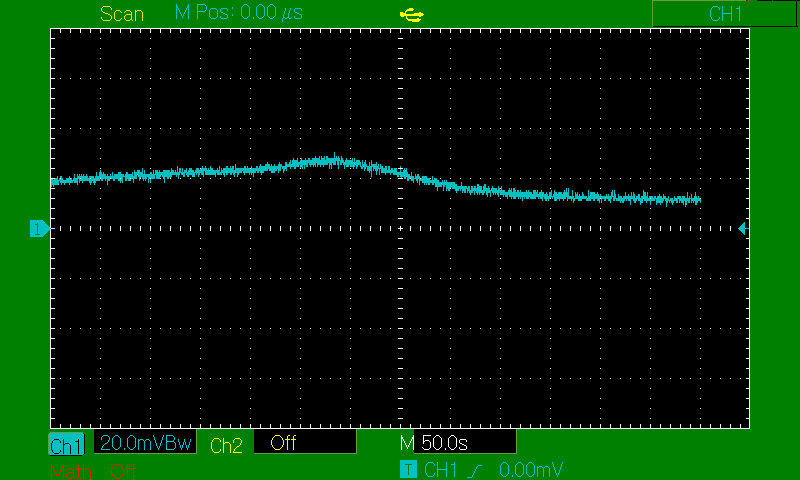
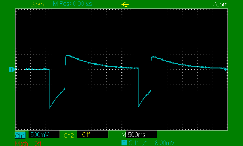
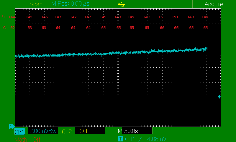
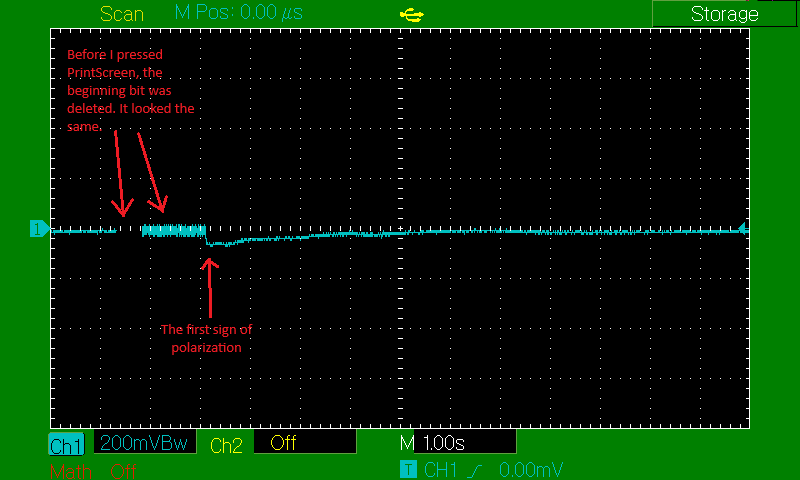
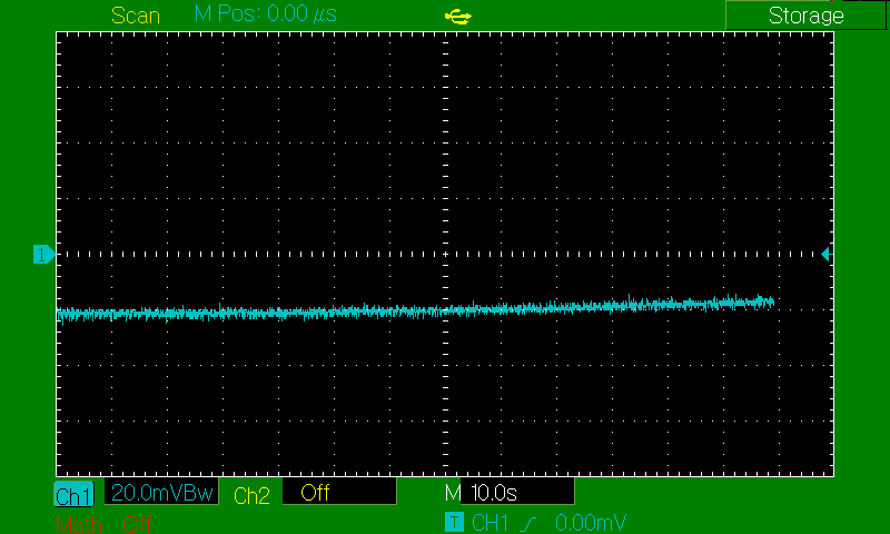
Now some more data from the scope on the first day. The probe 1x (1MOhm), DCmode. I left it connected for almost 20min as a load and monitored the voltage. Here are the screens.. (ignore the drops, bad connection)
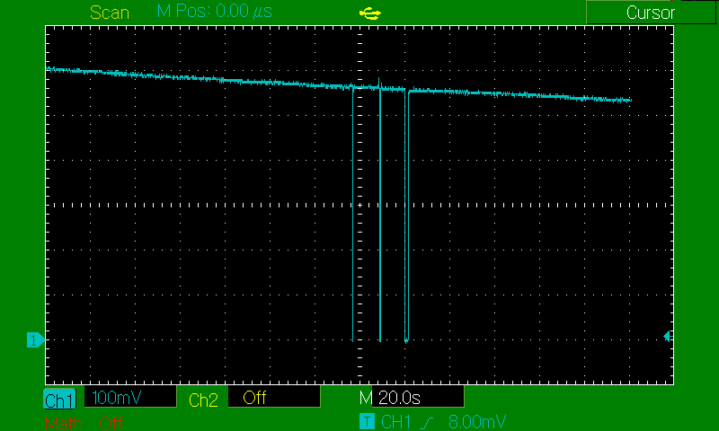
The voltage slowly, linearly, decreases (the scope shows less voltage than the multimeter because the probe is 1x/1MOhm).
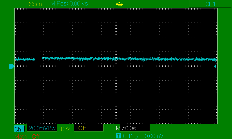
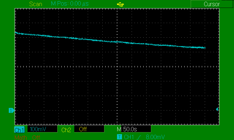
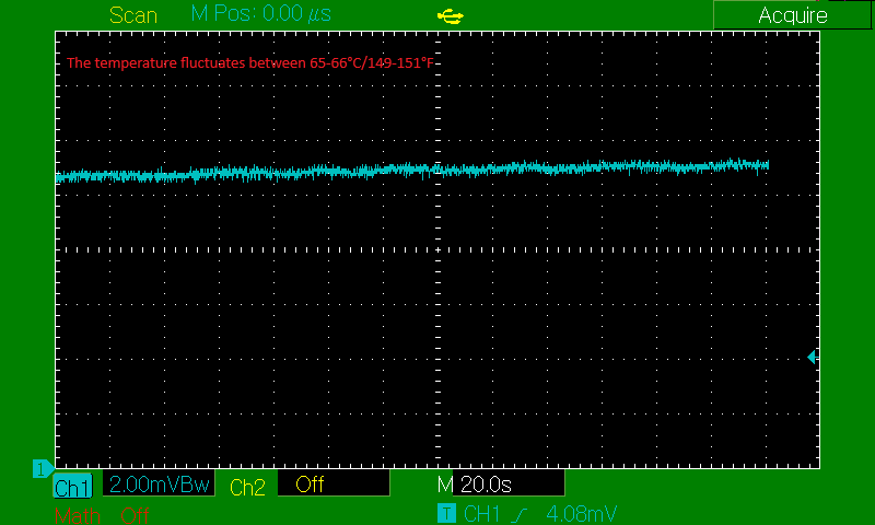
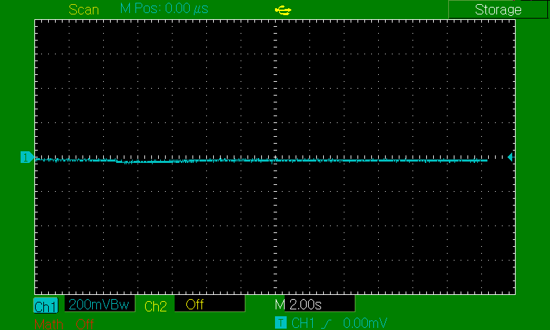
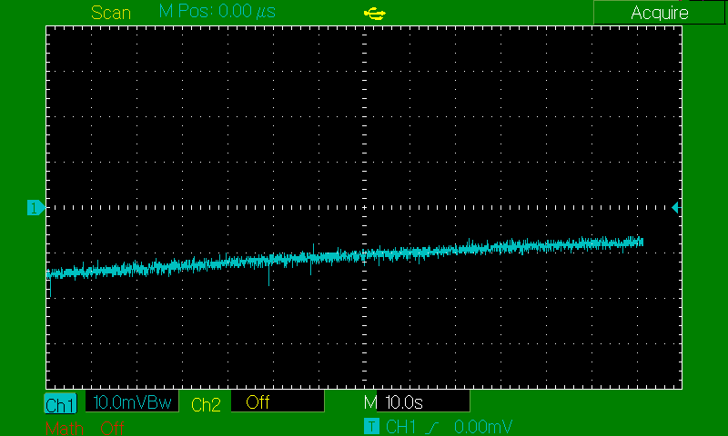
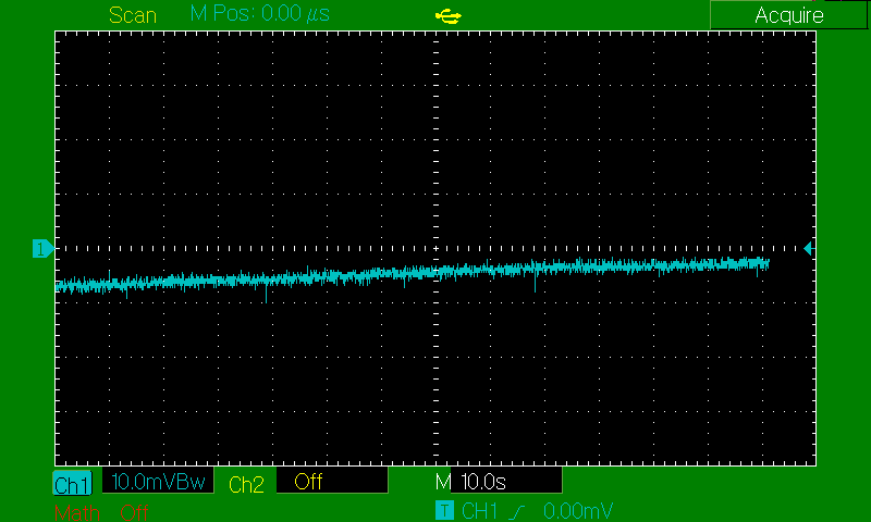
Then I switched the probe to 10x (10MOhm) and again monitored the voltage for some time.
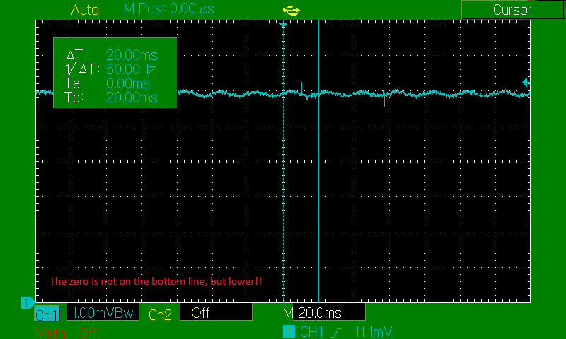
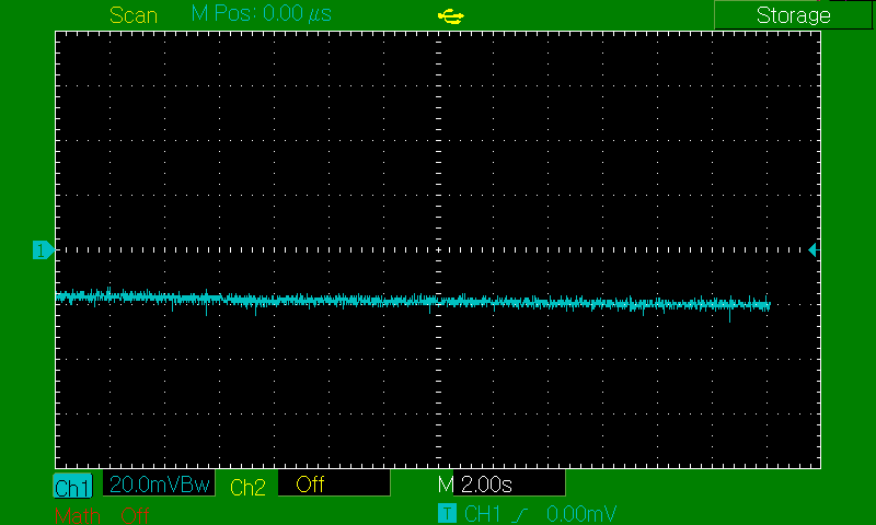
The voltage seemed more or less constant during this time. The small peeks and fluctuations are caused by noise (especially the mains 50Hz gets almost everywhere), but I'll come back to that later.
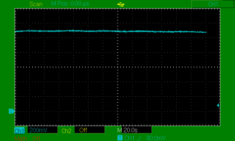
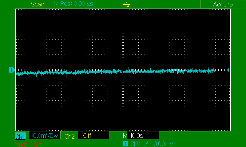
Reaction after short circuit-
Nothing unusual here.
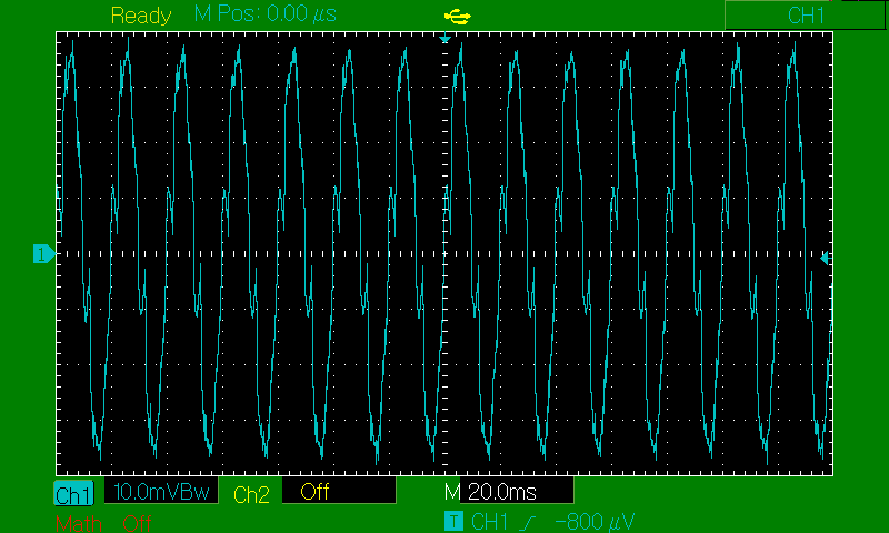
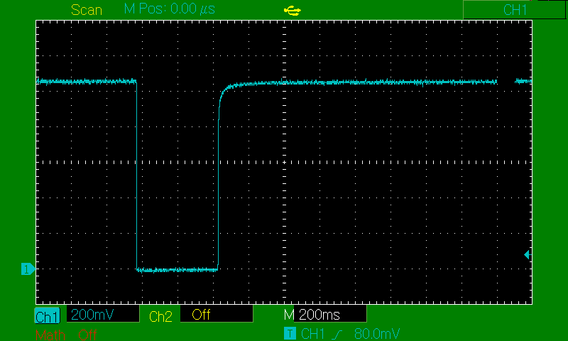
And finally, the legendary kickback Here in ACmod -
I gave the cell pulses of opposite polarity with an AA battery (+ to -,- to +). Here again, even in DC mode!
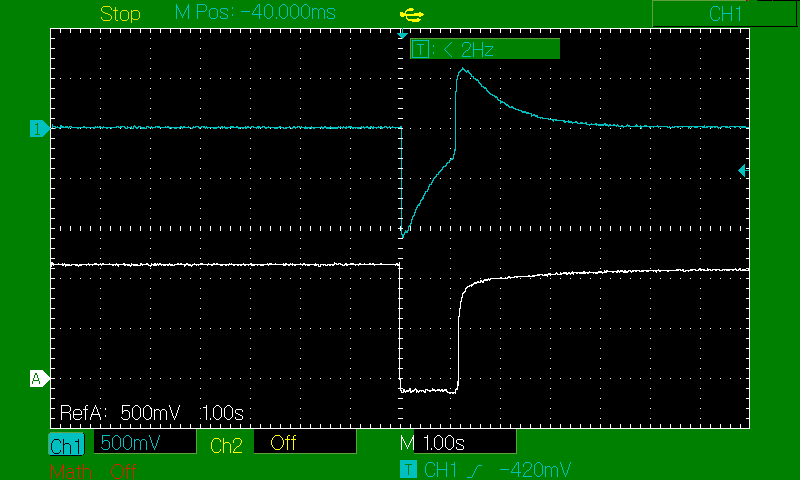
As you can see there is no kickback in reality. In DCmod (white), we see that the voltage changed to the value U=Ucell-Ubat for a moment, then increased again to the Ucell voltage. No kickback. This can be seen in AC mode because in AC mode there is a decoupling capacitor inside the scope in the signal path. With these pulse lengths (made by hand), the scope only sees the initial change and inversion of the voltage - a negative spike (Ubat>Ucell, Ucell-Ubat is negative), and then it sees the voltage jump back to the positive level of the cell - a positive spike. With any two voltage sources you can create this waveform on the scope in ACmod. So no unique property of PEG.
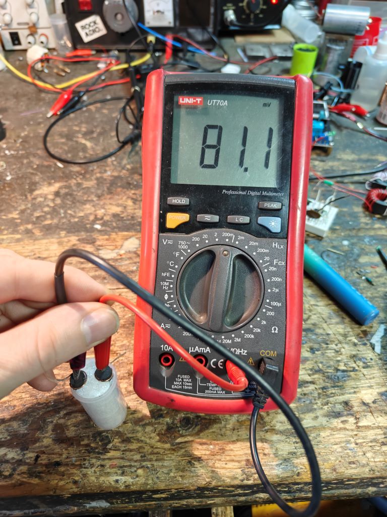
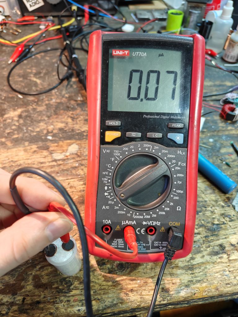
A few more photos from the measurements on Day 7 (I forgot the 6th day)
I have a lot more data, but this writing is taking more time than I expected. I found out something interesting but I still need to test it better. I will gradually post more..


 ). And the other interesting temperature seems to be when the PEG is liquid and hot, I'll try this one out.