Adams Motor-Generator

  • 517 Views
  • Last Post 7 hours ago
olli posted this 4 weeks ago

Dear researchers,

I would like to open a discussion about the Adams Motor-Generator in general and specifically my and others actual replication attempts.

Short intro to myself:
Since I got access to the internet in the late 90s the idea of overunity and "free" energy is thrilling me. So over the years I was sucking in every piece of information related to this topic - but only theoretically. One and a half year ago, after I got rid of my wife (what a waste of energy) and also being really anoyed buy this inflationary rise of "free" energy scammers, I decided to replicate one of those devices I knew already from my studies. I was not really choosing one, but coincidentally the device chose me - while I was again "researching", I stumbled upon the nexus magazine offer to buy/download the manual by Robert Adams: https://nexusmagazine.com/?s=robert+adams (I can give anybody a copy on demand).

I started to build my first motor-only device with LEGO Technic and some self-made coils and the original circuit by Adams. This was really fun and gave me a lot of confidence, that I am at least capable to create something "rotating".

...if you look carefully, you will see, that at this time I even was not really capable of properly setting up the scope šŸ˜Š.

Next was a more "serious" variation, where I designed some polycarbonate "housing" and put the coils between the rotors to use both sides of the coils...
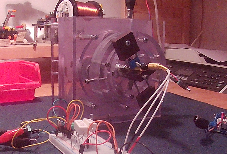
...even though this design seems better, I wanted to have some sort of flexibillity in terms of controlling all the aspects of the replication/research, e.g. changing the angle of the coils while running to see and tune - Adams mentions an angle of 20 degrees for the feedback coils, but I have the feeling, this angle is related to the actual duty cycle of the machine - so a rigid setup, where you have to shutdown, adjust or even reassemble things is just sucking.

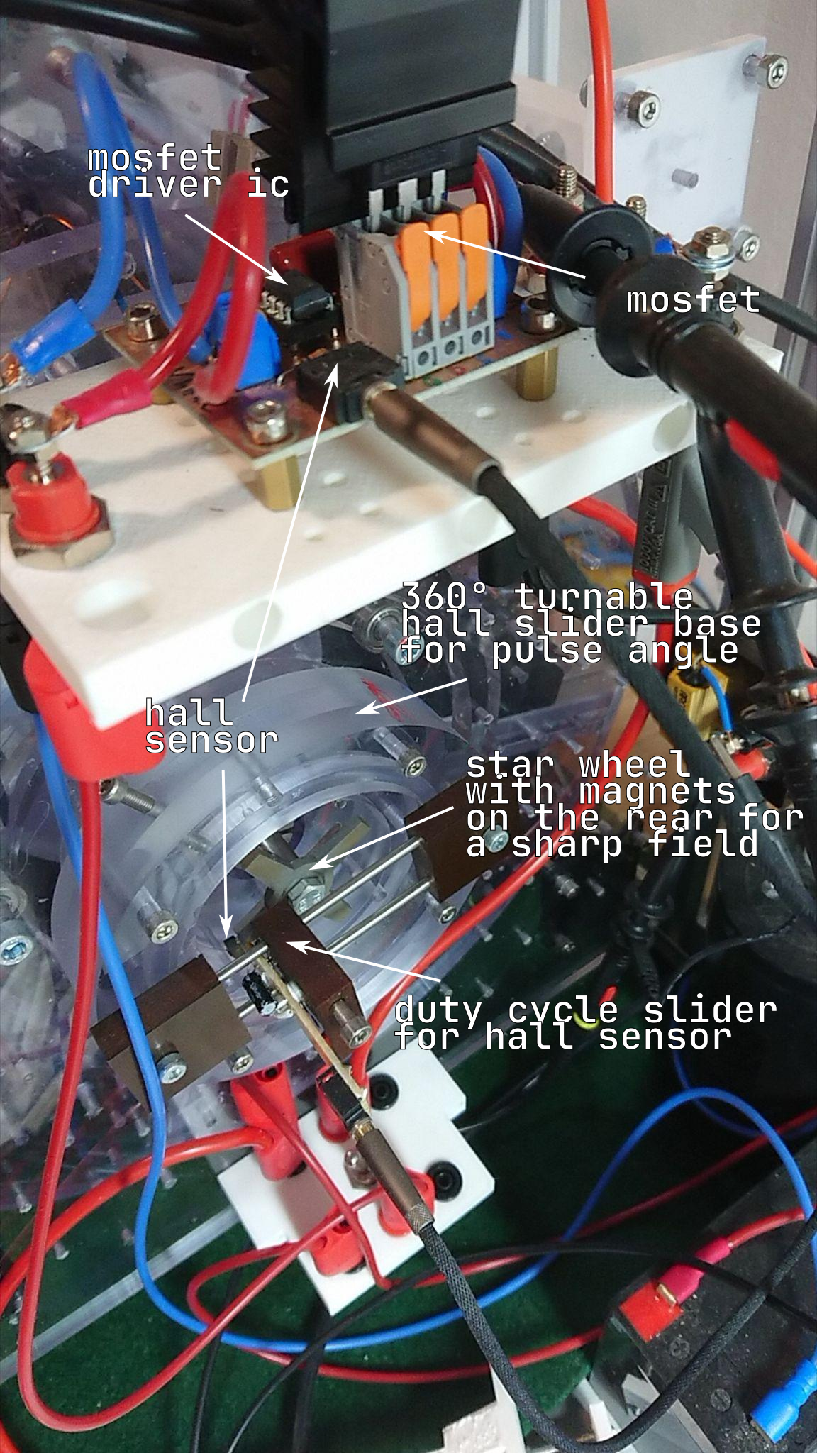
I came up with a better approach for my next design, where I am able to change coils in a reasonable amount of time and where I can rotate the coil stators 360 degrees while running and to change the duty cycle and the angle of the hall sensor... 
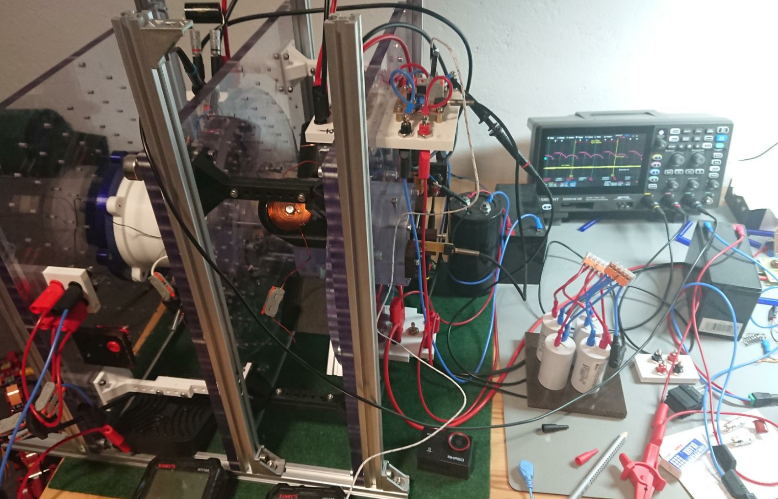
... for now I want to close this introduction...

Many thanks to the provider/operator of this forum - it is really hard to find people for exchange in this specific topics!

Olli

Order By: Standard | Newest | Votes
olli posted this 4 weeks ago

Dear researchers,

I would like to open a discussion about the Adams Motor-Generator in general and specifically my and others actual replication attempts.

Short intro to myself:
Since I got access to the internet in the late 90s the idea of overunity and "free" energy is thrilling me. So over the years I was sucking in every piece of information related to this topic - but only theoretically. One and a half year ago, after I got rid of my wife (what a waste of energy) and also being really anoyed buy this inflationary rise of "free" energy scammers, I decided to replicate one of those devices I knew already from my studies. I was not really choosing one, but coincidentally the device chose me - while I was again "researching", I stumbled upon the nexus magazine offer to buy/download the manual by Robert Adams: https://nexusmagazine.com/?s=robert+adams (I can give anybody a copy on demand).

I started to build my first motor-only device with LEGO Technic and some self-made coils and the original circuit by Adams. This was really fun and gave me a lot of confidence, that I am at least capable to create something "rotating".

...if you look carefully, you will see, that at this time I even was not really capable of properly setting up the scope šŸ˜Š.

Next was a more "serious" variation, where I designed some polycarbonate "housing" and put the coils between the rotors to use both sides of the coils...

...even though this design seems better, I wanted to have some sort of flexibillity in terms of controlling all the aspects of the replication/research, e.g. changing the angle of the coils while running to see and tune - Adams mentions an angle of 20 degrees for the feedback coils, but I have the feeling, this angle is related to the actual duty cycle of the machine - so a rigid setup, where you have to shutdown, adjust or even reassemble things is just sucking.

I came up with a better approach for my next design, where I am able to change coils in a reasonable amount of time and where I can rotate the coil stators 360 degrees while running and to change the duty cycle and the angle of the hall sensor... 

... for now I want to close this introduction...

Many thanks to the provider/operator of this forum - it is really hard to find people for exchange in this specific topics!

Olli

Vasile posted this 4 weeks ago

Nice build man ! If you have any pdf with more information on the subject, please post.

Jagau posted this 4 weeks ago

Hi Olli
Welcome to the forum
Yes the Adams engine is a very interesting subject, and it is beyond the unit.
I found some time ago a continuation and update of the book I bought on the Adams engine book, maybe it can help you also to understand.
Thanks for sharing what you do.
See pdf included.

Attached Files

Atti posted this 4 weeks ago

Hi Olli.

A lot of material on this topic can be found on the internet. Some years ago I did some research on this engine layout. 

You can see it here:

My opinion in short is.
Here is my brief summary. Take a carbon brushed small D.C. engine.  Drive it with PWM control. Measure the current drawn with a shunt resistor. Observe the oscilloscope diagram. 
Modify the arrangement by putting a fast diode at the output of your switching element and feeding it back to the supply voltage side while measuring this too. 
What do we see? When the controller turns off the supply voltage at the end of the pulse time, the voltage induced by the collapse of the magnetic energy accumulated in the coil produces a current equal to the battery current. This diode is now used to continue the motor current flowing through it during the pulse break.This diode is called a free-wheeling or flyback diode (for example in machine tools, but the MPPT controller used in solar PV systems is also similar). 
The current of this can be much higher than the current of the power supply in the right position. The Adams motor has the same problem. In addition, the speed of the motor is increased by the load in the correct position. Similar to the Raymond Kromrey alternator. You can see it here:

https://www.youtube.com/watch?v=O7jrTj1lk1U

Another interesting related topic. The layout is different but I think the reloading system is similar:


Atti.

Fighter posted this 4 weeks ago

Hi Olli,

Welcome to our site !

Sorry for my late post, I was on the road with limited internet access.

So you're a researcher and a builder, something very hard to find these days... šŸ™‚

You have very nice and sophisticated experiments there, you'll find this is the right place with real researchers you can exchange information with. No scams, fakes or other things like that here.

About the site, thank you for your kind words, it belongs to our team of researchers. We needed a modern platform with all the features necessary to exchange experimental results, documentation and ideas between the members of our team and share our research with the public.

For any questions related to the functionality/features of our site feel free to ask and I'll answer to your questions.

Regards,

Fighter

"If you want to find the secrets of the universe, think in terms of energy, frequency and vibration."
Nikola Tesla
Jagau posted this 2 weeks ago

Hi Olli


The interest of the Robert Adams motor/ generator has always been of great interest to me.
What you have demonstrated here interests me, when you have time tell me about the system that controls your impulses?

When I started with Arduino I found that this tool would be an excellent way to control the impulses which are the basic key of the Adams system. I would like to exchange with you on the impulse control system and show you my little program that could perhaps interest you and share other information.


Jagau

Jagau posted this 2 weeks ago

Hello Atti

I watched your video on the Adams motor  / generator, I liked it.

Do you have a schematic either hand drawn or otherwise of your Adams engine? I noticed some interesting things and I would like to understand better.
Thank you

Jagau

Atti posted this 2 weeks ago

Hi Jagau.

Well, clarify it so I can give you a better answer.  

I think everybody knows these, because there are a lot of Adams engine variations that you can read about.

But briefly, concisely.
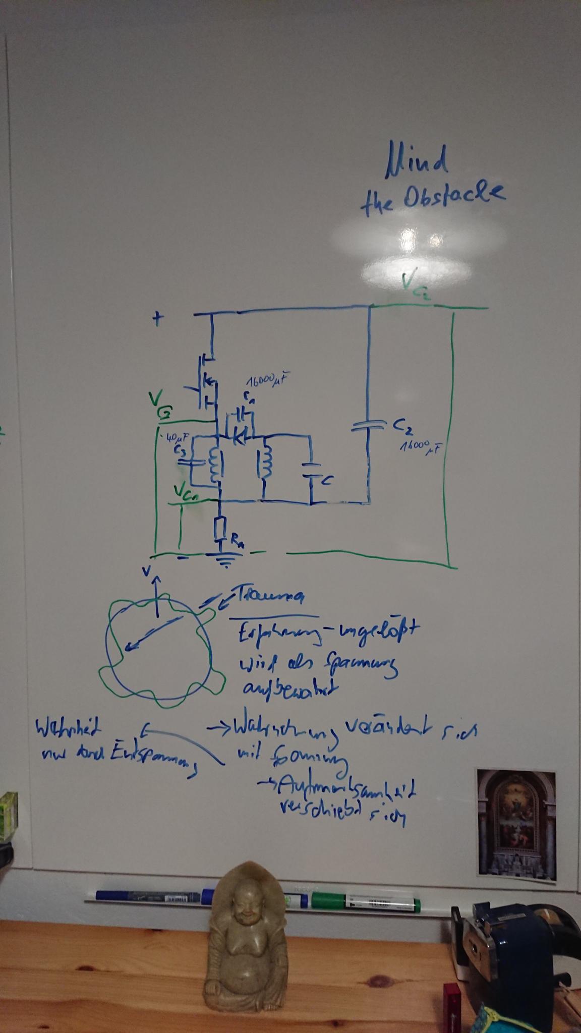
The wiring diagram is shown here:

The physical layout varies, but the essence is always the same.

So, there is a source battery. It pulses the stator coils. 
The stator windings are connected in series. They always point in the same direction towards the permanent magnet. It can be thought of as a loosely coupled coil (yes, there are similarities with other machines) 
 The thread numbers are identical on both columns.

  
It's all in the feeding.
As I said in the previous post.It is worth looking at the currents of a D.C, motor. Drawing:


Surprising. But if you also tie the disconnect to a similar battery you may find that the disconnect current is more.


Atti.


Jagau posted this 2 weeks ago

Really interesting Atti. I think Olli will be too.

This project has always interested me and I think I'll make a thread on this subject. As the parts of another important project are in back order I will look at this one seriously.

I had already started the engine some time ago, I had put it aside, but I think this would be the ideal time to build it and start it. The subject is very topical because the Adams generator is overunitary.

Jagau

olli posted this yesterday

Please appologize my silence... Life and its obligations are eating up all my time. Thanks you for your responses! I have attached all my documents regarding the Adams-Motor-Generator to the initial post (easier to find), sadly their filenames are hashed and nobody knows what is inside (maybe the operator has a way/plugin to overcome this limitation)...

What is, since the beginning, really sucking on my nerves, frustrates my endeavor and basically stops progress, is: WINDING COILS

How are you guys dealing with the linearly increasing tension of the wire when you add layer after layer? This "problem" is sometimes pulling/slipping the wire into the layer underneath and so introducing a kind of winding bug, which affects all layers above in an exponential way...
 I use a magnetic brake and a PWM speed control which I turn down every layer, which results in a linearly increasing time, each layer needs... Are you winding by hand? Or are you not caring that much for the introduced losses of "imperfect" coils?

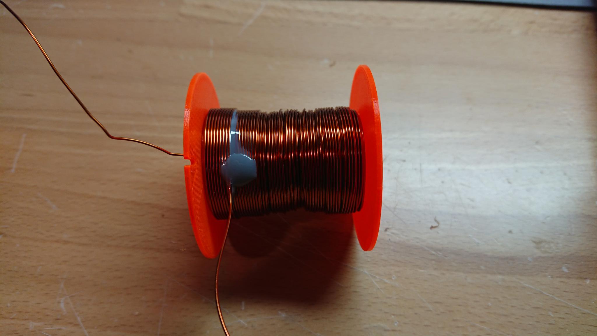
This coil (0.6mm wire, 40mm length) is an example, where I stopped at 875 turns:


There is already a convincing product for this problem (but I guess unaffordable for a private engineer and researcher): https://www.coilwindingmachines.eu/wire_tensioners/servo_wire_tensioners_video_demonstration.html

...since I am software engineer, my latest inspiration,thoughts and investments are circulating around building something with an esp32 or arduino, a linear hall sensor and a "magnetic spring", to detect the tension and control the servo motor...

Olli

Fighter posted this yesterday

Hi Olli,

No worries and no apologies needed, for the same reasons we all fight to find time to work on our experiments...

About winding the coils, personally I also don't have any machine for this, I build the coils manually.

I'm a software developer too but I think building a winding machine would take too much from my already limited time.

So my coils are never perfect, especially when there are many layers needed, but they're good enough for what I need in my experiments.

Regards,

Fighter

"If you want to find the secrets of the universe, think in terms of energy, frequency and vibration."
Nikola Tesla
Close