Adams Motor-Generator

  • 1.9K Views
  • Last Post 15 February 2025
olli posted this 22 August 2024

Dear researchers,

I would like to open a discussion about the Adams Motor-Generator in general and specifically my and others actual replication attempts.

Short intro to myself:
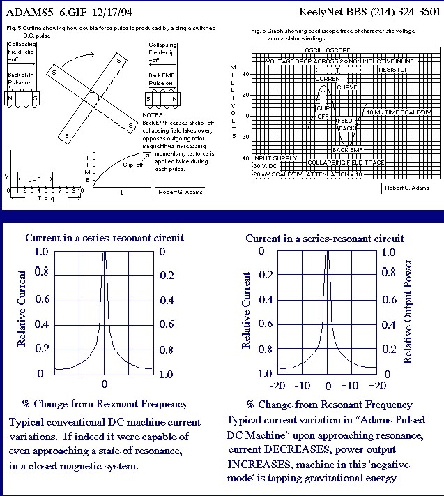
Since I got access to the internet in the late 90s the idea of overunity and "free" energy is thrilling me. So over the years I was sucking in every piece of information related to this topic - but only theoretically. One and a half year ago, after I got rid of my wife (what a waste of energy) and also being really anoyed buy this inflationary rise of "free" energy scammers, I decided to replicate one of those devices I knew already from my studies. I was not really choosing one, but coincidentally the device chose me - while I was again "researching", I stumbled upon the nexus magazine offer to buy/download the manual by Robert Adams: https://nexusmagazine.com/?s=robert+adams (I can give anybody a copy on demand).

I started to build my first motor-only device with LEGO Technic and some self-made coils and the original circuit by Adams. This was really fun and gave me a lot of confidence, that I am at least capable to create something "rotating".

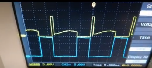
...if you look carefully, you will see, that at this time I even was not really capable of properly setting up the scope šŸ˜Š.

Next was a more "serious" variation, where I designed some polycarbonate "housing" and put the coils between the rotors to use both sides of the coils...

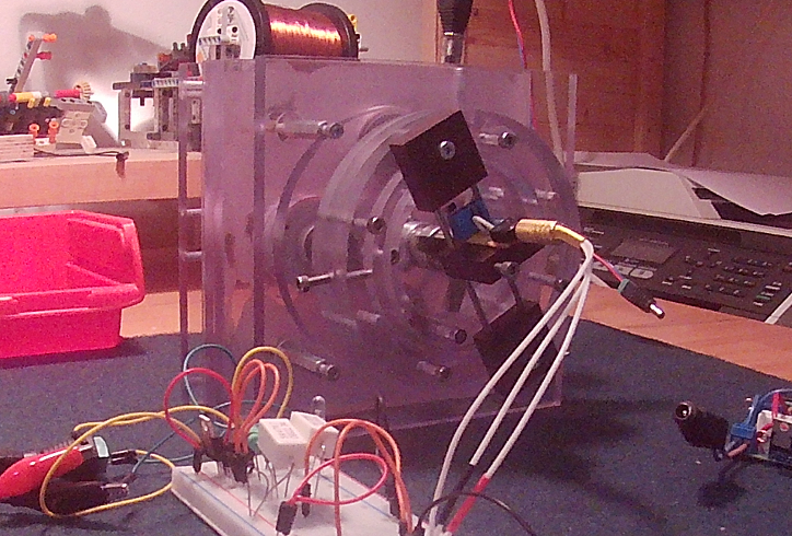
...even though this design seems better, I wanted to have some sort of flexibillity in terms of controlling all the aspects of the replication/research, e.g. changing the angle of the coils while running to see and tune - Adams mentions an angle of 20 degrees for the feedback coils, but I have the feeling, this angle is related to the actual duty cycle of the machine - so a rigid setup, where you have to shutdown, adjust or even reassemble things is just sucking.

I came up with a better approach for my next design, where I am able to change coils in a reasonable amount of time and where I can rotate the coil stators 360 degrees while running and to change the duty cycle and the angle of the hall sensor... 

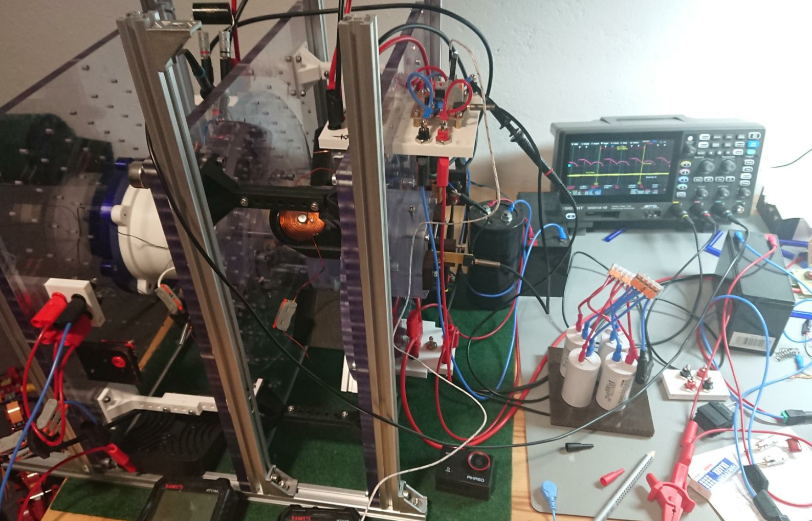
... for now I want to close this introduction...

Many thanks to the provider/operator of this forum - it is really hard to find people for exchange in this specific topics!

Olli

Vidura posted this 15 September 2024

Hi Olli, Neatly built your motor-generator. 

How are you guys dealing with the linearly increasing tension of the wire when you add layer after layer? This "problem" is sometimes pulling/slipping the wire into the layer underneath and so introducing a kind of winding bug, which affects all layers above in an exponential way...

Regarding the windings, I use a coustom made winding maschine made of a 12v drillmaschine, I have adapted a speedcontroller with a pedal for regulation, so I can use both hands to handle the wire. I give the wire tension by sustaining it with gloves or a peace of wood. The layer problem I could resolve by placing a paper tape over each layer to avoid the wire going in between the former  layer.

Regarding the resonance issue, I am pritty sure that Mr. Adams mostly referred to magnetic resonance, as his presented circuit diagrams are very simple and do appearently not represent LCR resonant systems. As he stated a torough fine tuning is nececary to bring the maschine in this condition. Anyway In my opinion it should be possible to achieve cop>1 also out of resonance, altough not with the same performance. Later I will post some hypothesis about the principle which might be involved, and also an idea about a controlled resonant motor.

Regards 


Vidura

Atti posted this 16 September 2024

Hi Jagau.


 I noticed some interesting things and I would like to understand better.


What do you think is interesting? What exactly do you mean?

Atti.

Jagau posted this 16 September 2024

As you know I am building this motor and noticed in this picture that you are using the fall time of the hall sensor to activate your mosfet.

There are different ways to activate the mosfet, either by state change, by rise time or fall time, I was wondering how you did it that's all.

Found this interesting your switching method.

We can see at the end of the fall time that there is no lag in the switching which is what I found even more interesting.

Because the time the Hall sensor detects the position of the magnet plus the switching time on the mosfet gate and the switching delay of the mosfet itself is there and this is what I found the most difficult to adjust for now.

Jagau

olli posted this 07 October 2024

Hey guys,

I was stepping back a bit and reviewed my work and the material Adams provided. I came to the conclusion, that I have to research and compare the rotor design Adams suggests and what I have made up from this information...

Since I think I discovered a crucial aspect of the whole working principle, I want to share this with you and maybe somebody can confirm/test/replicate the differences in both designs. My next steps are to build a small lego motor/generator around this neworiginal rotor.


Olli

Jagau posted this 08 October 2024

Hi Olli
I think the free force also comes from the fact that the pulse is applied twice to each magnet while creating a BEMF which can also be used to lower the input power.
As in the example Adams provided us here in this image.

There is also as in the video of Vidura demonstrated the natural attraction of the magnet on the iron which is also a free force which increases the momentum of the rotor.

Jagau

Unimmortal posted this 11 February 2025

Hey guys, new here and wanted to post a few of my thoughts as I've been working on my variant of the Adams generator for the past few years and have learnt a lot.

https://www.youtube.com/@unimmortal6352

Jagau posted this 11 February 2025

Hi unimmortal

The Adams engine is always interesting and current.

Julian Perry's managed to achieve an efficiency between 5 and 8 with an Adams type pulsed engine, at end of page 5 on lower link.

see some try here:

 https://www.beyondunity.org/thread/energy-gains-in-adams-patent/

You are welcome on the site.

Jagau


olli posted this 11 February 2025

Replying To: Jagau

...sorry for the late response. The time I switch the mosfet can be adjusted by turning the angle of the hall sensor in relation to the angle of the rotor. So to say my hall sensor has no fixed position and I can turn it while running the motor - so I can basically choose the spot where max torque vs. input power is...

...but as I tried to point out in my rotor research video, I think it is absolutelly necessary to use long magnet rods reaching to the center of the rotor, since the flat magnets exhibit a torque-free-zone from 25% to 50% duty cycle (like Adams proposed). After trying out Adams' rotor design there is not much need anymore to adjust the position of the hall sensor (at least experiment showed, that the "best" spot is not far from the magnet center (I guess mosfet switching latency is the only thing to adjust for). I am actually building a smaller motor from printed parts and hope, that I can soon update you guys on the results...

@admin I seem to be a bit too stupid to embed youtube videos - I always get "No video with supported MIME type found."

Fighter posted this 13 February 2025

Hi Olli,

Sorry for the delayed reply.

No worries, I fixed the YouTube video you wanted to insert in your post.

Usually I correct them when I find links which are not working for YouTube videos.

For YouTube videos you don't need to use the Insert Video functionality.

For posting a YouTube video the video address must be added in a new line in post as a simple text and the site will detect it as a YouTube video and will render it accordingly:

If you have any problem or have questions about the site functionality don't hesitate to ask.

Regards,

Fighter

"If you want to find the secrets of the universe, think in terms of energy, frequency and vibration."
Nikola Tesla
Jagau posted this 15 February 2025

Hi Olli
After watching your video, I think you are right, the magnets must be on the entire length of the disk. Besides, Adams himself has always demonstrated in these images magnets on the length.

If we look closely at the arrangement of the magnets on the disk, the permutation, instantaneous change of polarization, is done in the axial and not radial direction with the two magnets aligned with the iron and the coil which conducts the impulses.

The magnetic force of the magnets is axial and is exerted in a parallel or longitudinal way. The two magnets in line with the iron core and the coil pulsed. The radial force is on the side at 90 degrees is produced the inertia or mementum of the motor. The axial force powers the motor and the radial force is the resultant of the axial force.


I will remake another disk with 4 standard ferrite magnets and look at the difference in consumption and performance.

Jagau

  • Liked by
  • Inception
  • Fighter
Close