About electric motors, generators and magnetism

  • 559 Views
  • Last Post 5 days ago
Vidura posted this 11 September 2024

In this thread I will present some video material from Peter Lindemanns Movie “Electric motor secrets”. As the videos found on You tube had a synchronisation issue with the video and soundtracks it was very hard to understand and follow the presented material, so I will post here the edited video in three parts. It should give some inspiration to discuss the presented concepts and ideas, verify with own experiments and try to figure out some more secrets about magnetism and its interaction with electric current.

So here are the three videos “Electric motor secrets”:

In the second part I have commented a few things, which reflect only my personal opinion, but as far as possible I will try to present experimental results proof the statements.

Find attached below the patents of Robert Teals Magnipulsion engine:

Vidura

Attached Files

Order By: Standard | Newest | Votes
Vidura posted this 11 September 2024

In this thread I will present some video material from Peter Lindemanns Movie “Electric motor secrets”. As the videos found on You tube had a synchronisation issue with the video and soundtracks it was very hard to understand and follow the presented material, so I will post here the edited video in three parts. It should give some inspiration to discuss the presented concepts and ideas, verify with own experiments and try to figure out some more secrets about magnetism and its interaction with electric current.

So here are the three videos “Electric motor secrets”:

In the second part I have commented a few things, which reflect only my personal opinion, but as far as possible I will try to present experimental results proof the statements.

Find attached below the patents of Robert Teals Magnipulsion engine:

Vidura

Attached Files

Vidura posted this 11 September 2024

Here I have carried out some very simple experiments with electromagnets and magnetic circuits:

It can be clearly noted that opening and closing the magnetic circuit changes the current drawn from the electromagnet in both directions. As per ohms law the current depends on the wire resistance, it is clear that energy is exchanged when the magnetic loop is altered. It is also evident that energy can remain as magnetic flux for apparently unlimited time in a closed magnetic loop, without any current being present in the adhered coil winding.


Vidura

Vidura posted this 11 September 2024

Here two more very short experiments to colect more information about the properties of the magnetic flux loop:

Magnetic experiment 2

Magnetic experiment 3

In this experiment I tried to figure out the the limit size of the gap to sustain the magnetic holder effect. With 0.01mm -0.03mm it remains like without the gap. Up to 0.05mm the attraction force is slightly diminished, and with 0.1mm(paper) it is barely perceptible and dies out after an instant

Vidura

Vidura posted this 5 weeks ago

Some concepts about motors and the attempt to overcome the issue of the BEMF. As we saw in the first part of Peter Lindemanns movie, the conventional motor is always acting as a generator as well. This generated BEMF works against the efficiency of the motor. Therefore we should generally not strive for the highest RPM of the motors, as in this condition the COP is the lowest. As the motor is loaded it slows down and generates less of the adverse BEMF raising the performance of the maschine.  In this statement I agree with him, but I disagree in the part where he says that a magnetic attraction motor do not generate anything, this is only true while the electromagnets are turned off. At the moment when a piece of iron is exposed to a magnetic field it becomes magnetized itself and thus produces an BEMF when approaching the coil or moving away from it. Note that using iron it becomes always magnetized in attraction mode, which causes the produced BEMF in the coil to be in opposite direction as the applied voltage when approaching the coil (current decreases) and in the same direction when moving away (current increase). This is true for all conventional motors also AC induction motors and including the most efficient of them, the switched reluctance motor. The last mentioned do not virtually generate any BEMF while it is under constant load in locked state, but when the load is changing the same effect appears producing the changes of current in the coils.

So, one concept to overcome this is the implementation of the magnetic repulsion motor, which has been adopted by Robert Adams and John Bedini for example. In this case the armature has to be constructed with permanent magnets or other sets of electromagnets. It is supposed that in this configuration the generated BEMF would assist the applied EMF to the motor instead of working against it.

What is the difference of a magnetic motor to other magnetoelectric devices like transformers?

I think the most important difference is that in the case of the motor we can find engineer solutions to take advantage to transform a “static magnetic field” into useable work. Of course, power is used to turn the magnet on, then it would be sufficient to overcome the I2R losses during the work cycle, and a significant part of the current could be recovered at switching off.

All this still do not involve the resonant phenomenon, which could bring this machine still to another level. It opens the doors for techniques of very high currents with a great potential of energy recovery, and small I2R losses with the usage of thick conductors.

Vidura

xman posted this 4 weeks ago

Have you seen this document by hoptoad on ou.com? I don't know why it was deleted. Maybe it worked, maybe it didn't. He said the secret is in the core material and length. I haven't done this experiment.

Attached Files

Vidura posted this 4 weeks ago

Replying To: xman

Actually I dont visit the OU.com site. But the effect is known, if you have a magnetic pole tester or a small compass you can check the influence of the corelenght, material and geometrical shape.

Here another short video with an experiment on magnetic flux properties:

Magnetic experiment 4


Vidura

Vidura posted this 4 weeks ago

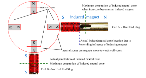
Now I will explain a little more in detail the concepts which can lead us to construct a superefficient motor using the magnetic force properly. In the third part of the video above an explanation was given about the energy balance of a drive coil when the energy stored in the inductor is recovered. Similar methods of implementation have been used by Roger Andrews, John Bedini and Peter Lindemann, let me comment something more about this, as there might be the key to get these machines self-sustaining and producing excess energy. It is quite obvious that the magnetic field from a permanent or electromagnet can perform work attracting or repulsing another magnet or simply attracting a piece of iron. It should be also clear that the magnet or magnetic force is not depleted by such an action. But of course, to make this work usable we must be able to switch the magnet on and off, and this suggests that it could be done easier with electromagnets. But there are some challenges to overcome.

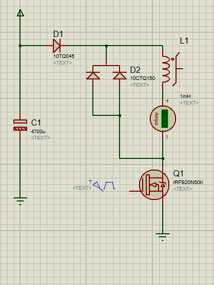
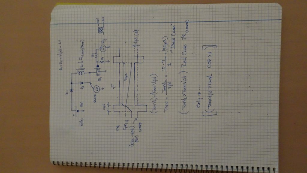
Here below a screen clip from the video:

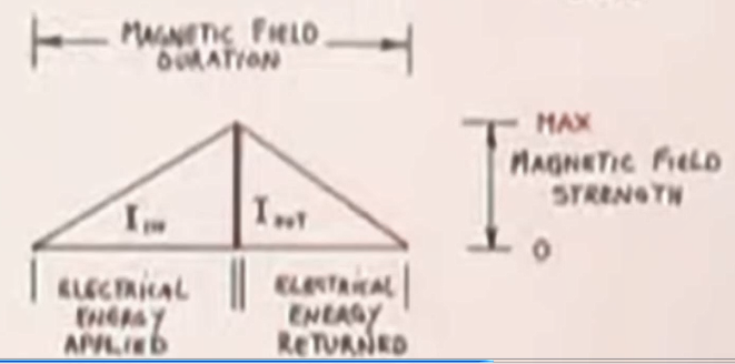
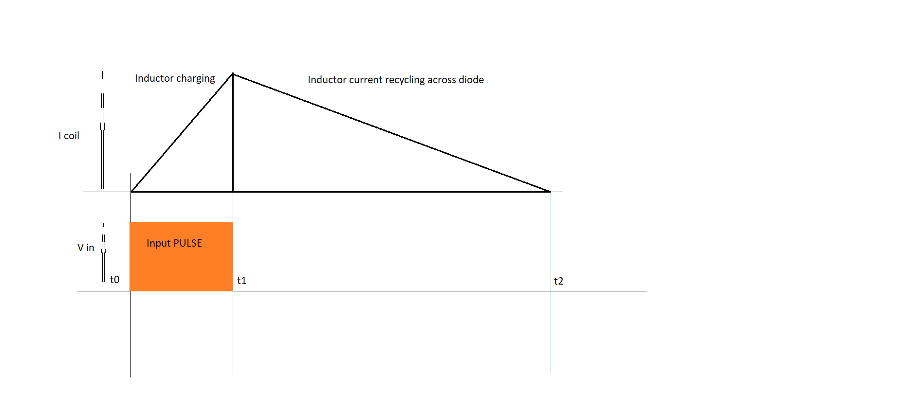
The triangle represents the current ramp in a drive coil, and the magnetic field strength is proportional to the current. Energy has to be fed into the inductor from the beginning of the pulse until reaching the maximum value, then, at switching off the energy stored in the inductor (less losses) can be recovered with a properly designed circuit. But I argue that the current-magnetic field strength is in average over this period only 1/3 of the maximum which limits the practical usable force for a much shorter period. It could be improved by using large inductance to extend the period, but at the cost of longer wires, more expensive materials and increased I2R losses and not really addressing the issue.

Anyway, the argument that the stored energy can be recovered is valid. But can this be done in a better, more efficient way? The answer is Yes, and there is more than one way to do it. 

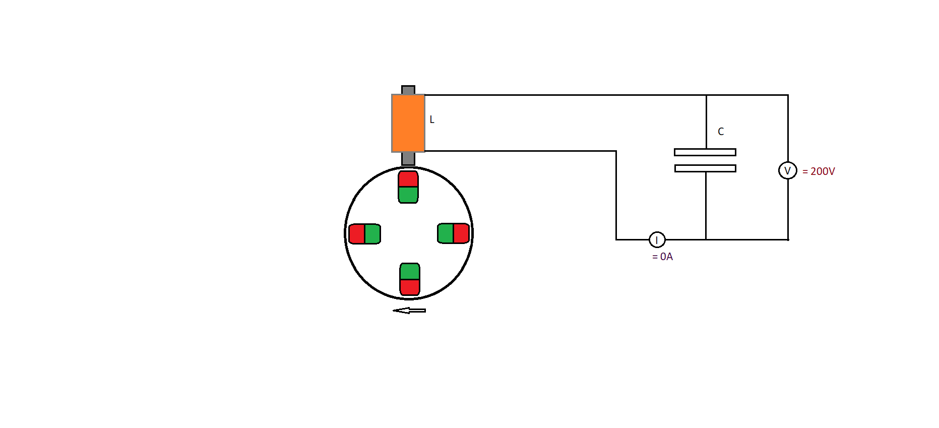
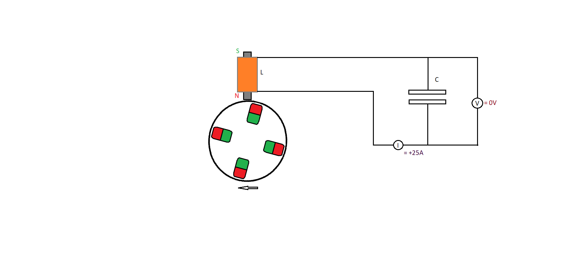
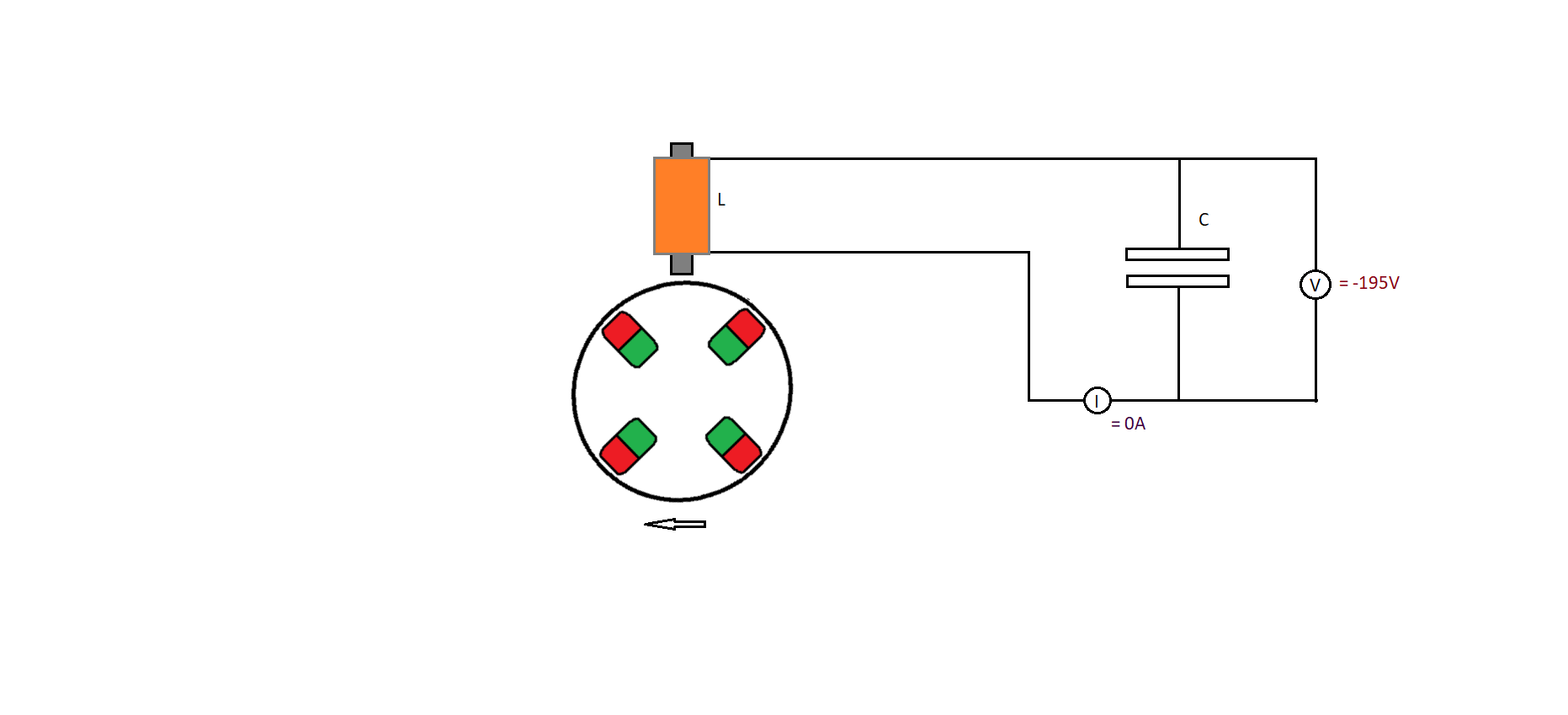
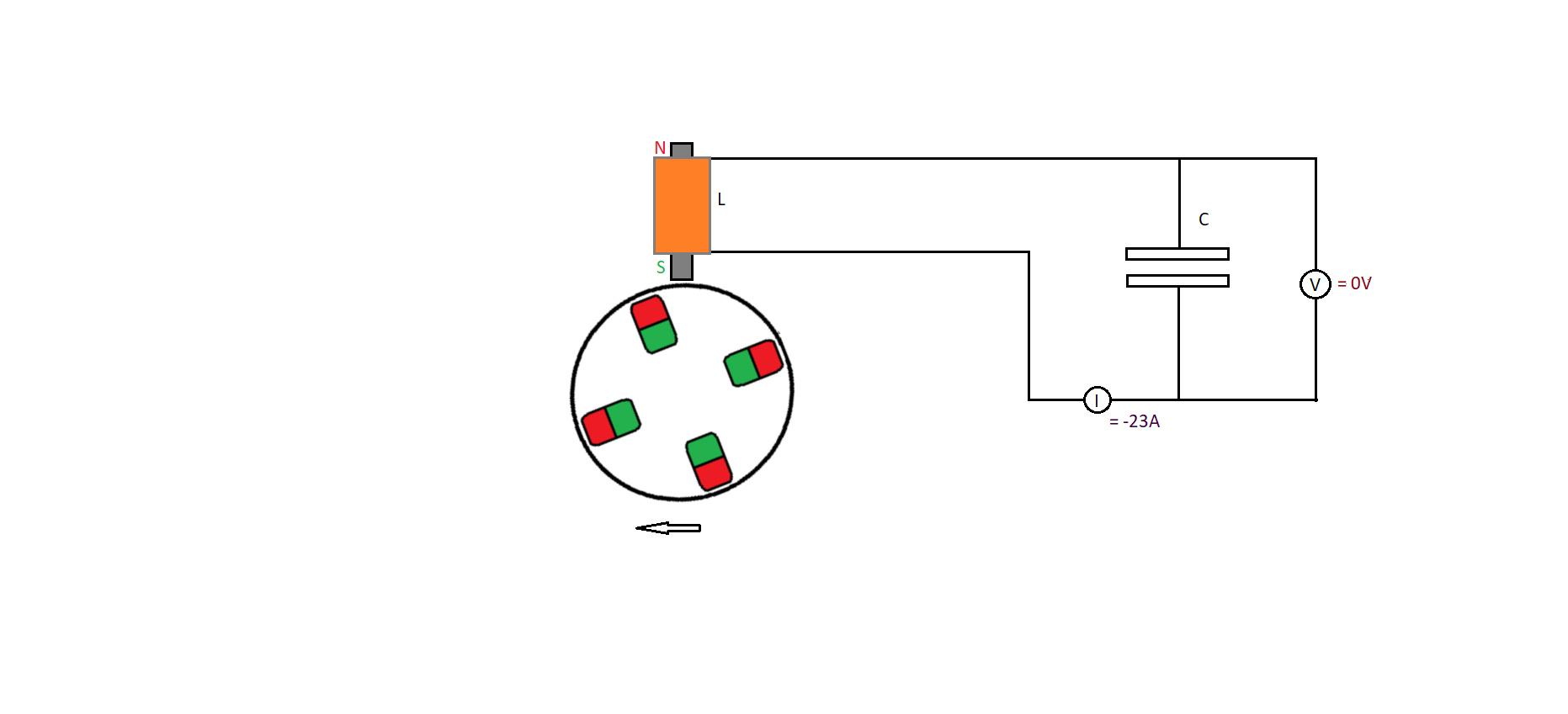
When I experimented with a pulsmotor similar to Bedinis designs I found out that the lower the impedance of the current recovery circuit is, the longer the current and magnetic field remains. This means for example if we dump the stored energy of the inductor at switching off into a battery with lower voltage rating, the motor gains force.  In the diagram of current the triangle would extend to the right side. So, for the same electrical input we will have available the magnetic force performing work for a longer period. This can be further improved reducing the impedance to an insignificant value, for example with a freewheeling diode in parallel to the inductor. In this case the duration of the work period would be only limited by the I2R losses. There is no magic in this, it is well known in electrical engineering. To get a magnetic field from an electromagnet only current is needed, the voltage is only required to accelerate the charges, once they are in movement the magnetic field is produced for free!

Of course, the solution of the batteries or freewheeling diode have still its drawbacks, but I think that with a well designed and tuned hardware some have succeeded already with such simple approaches. In another post I will present some more refined ideas for the implementation of the concept , which I took as basis for the practical part of the Adams motor replication.

Vidura

Vidura posted this 4 weeks ago

Those experimented in electronic engineering will know all this for sure, but for more clarity I will put a schematic:

 and an approximate graph of the current using a freewheeling diode in parallel to the inductor: 

The right side of the triangle represents the current after switching off(t1-t2), decreasing only cause of the I2R losses of the wire and the diode. The drawing is simplified, in the actual shape it would fall slower towards the end of the ramp, as the current becomes smaller also the resistive losses decrease.

Despite that this methodology makes it possible to generate a magnetic field during a much longer period of time for the same input, it still has drawbacks for the implementation in pulse motors. Most important it is not possible to adjust the effective magnetic duty cycle, therefore at best it could be tuned for a fixed RPM value. The energy of the inductor has to be depleted completely without possibilities to recover. 

There are still better solutions to address the challenge of getting out the best magnetic performance of a short input pulse.

The following approaches will involve resonant phenomenon in the circuit design, so we will be able to get an extended time period of magnetic action and will also be able to recover a significant part of the input energy. Another advantage of a resonant system is the possibility of get huge reactive currents for a relatively small input, so the windings can be made with less turns and thick wire gauge for a better Q-factor.

In the next post I will explain this more detailed.


Vidura

Vidura posted this 4 weeks ago

Resonant driven motors:

It is straightforward to understand how to drive an AC motor in resonant mode, so lets analyse this case first. Look at the diagram of an LC resonant circuit below, for simplicity the electronic driving part is not shown, so we can only focus on the magnetic interaction with the rotor. 

The first drawing shows the initial state when the capacitor is fully charged

In the second drawing the capacitor is fully discharged and the current at it’s maximum value. The drive coil is repelling the magnet in this case.

In the third drawing the current is at zero and the capacitor is charged in reverse polarity to a slightly lower voltage cause of resistive losses.

The fourth drawing shows the current maximum in reverse direction, a little attenuated cause of the losses. The electromagnet now attracts the rotor magnet.

Then the cycle repeats, and the capacitor would be topped up to the initial value by some circuitry. We could expect a very good COP from a motor of these characteristics. The obvious drawback is that it would work in resonance only at a unique RPM rate. It would self-regulate for the upper limit, but needs some help to start up until it locks into the LC resonant frequency and might loose the lock condition under varying load conditions. In the next post we will analyse implementations of resonance for DC pulsmotors. 

Vidura

YoElMiCrO posted this 4 weeks ago

Hello everyone, an observation...

In today's systems, no matter what it is, the law of conservation of energy applies
In the following way, we observe the areas in the same frame of reference.
This image I think explains better what has been stated above.

YoElMiCrO.

Vidura posted this 4 weeks ago

 Thank you YoElMiCrO for the correct formula to calculate the energy in an inductor.  Of course, I do not expect to get OU out of an electromagnet, neither from a permanent magnet. The energy of the magnetic field comes from space, not from the power pumped into the electromagnet or in the permanent magnet during its fabrication. Therefore, the magnetic field do not diminish by performing work. For this reason, I did not account for the voltage in the above circuit diagrams, although it must be included at the moment of designing a practical implementation. But for the purpose of setting up a magnetic field we must focus on current. Despite that the voltage at recycling becomes negligible or including non-existent in a closed conductive loop, the magnetic field remains as long as the current flows.

In more simple words for the case of the pulsmotor with freewheeling diode: we have to pump power into the driving coil, current and magnetic field strength are ramping up. When the desired intensity is reached, we turn off the power and recycle the current into the driving coil. During the recycling period the remaining energy stored in the inductor is used to sustain the magnetic field until it is depleted in I2R losses. The energy recovered in this second period will be less than the initial pulse. But we can use the force of our driving coil during both cycles. So, we don’t bother about if only say 85% of the initial pulse energy is reused in the second period, because we can extend the duration of the magnetic force to many times the duration of the input pulse. This means we can get a large(magnetic) duty cycle in the motor for a small input pulse.

Vidura

Close