About electric motors, generators and magnetism

  • 559 Views
  • Last Post 5 days ago
Vidura posted this 11 September 2024

In this thread I will present some video material from Peter Lindemanns Movie “Electric motor secrets”. As the videos found on You tube had a synchronisation issue with the video and soundtracks it was very hard to understand and follow the presented material, so I will post here the edited video in three parts. It should give some inspiration to discuss the presented concepts and ideas, verify with own experiments and try to figure out some more secrets about magnetism and its interaction with electric current.

So here are the three videos “Electric motor secrets”:

In the second part I have commented a few things, which reflect only my personal opinion, but as far as possible I will try to present experimental results proof the statements.

Find attached below the patents of Robert Teals Magnipulsion engine:

Vidura

Attached Files

Vidura posted this 3 weeks ago

Resonance in a DC pulsed motor:

What if we want to drive our motor with pulses of only one polarity, for example always in repulsion mode, and we want to do this in resonant condition?

To understand the phenomenon of resonance in DC circuits first we have to define the meaning of resonance in an oscillatory circuit. Such circuit is able to change periodically between two states, in our example potential energy  and movement of charges- current. The time period depends on the values of the capacitor and the inductor and defines the self-resonant frequency of the circuit. Conventionally resonance referred to the phenomenon when any oscillatory system is activated by an external source matching the resonant frequency. In most cases the external source is injecting at a lower power rate and the resonant oscillations are increasing cycle by cycle. The limits are given by the Q-factor and maximum ratings of the components, current limit of the inductor and maximal admitted voltage of the capacitor. But this is not the only possible case of resonance.

There are some implementations of DC resonance, for example the resonant charging choke. Here the resonance between the capacitive and inductive components is driven in one single unipolar interaction to reach its maximum value. In those circuits electronic switches and rectifiers are used. It is still a resonant event, because the inherent time period of the circuit corresponds to the self-resonant frequency. This technology is used for example to pulse the huge electromagnets of particle accelerators, you can find more information on the internet.

Another implementation of resonance in DC circuits can be achieved with electronic switching by means of synchronous rectification to feed DC halfwaves into the electromagnet as for our motor example. 

The advantage of the electronic switched resonant circuits is that they can provide solutions to adjust the system to varying speed and load conditions, while maintaining in resonance. I will come back to this with an example.

Vidura

Jagau posted this 3 weeks ago

More and more interesting, excellent discussion Vidura.

I would add if you allow me that what most researchers forget is that resonance must be itself in resonance with the enormous energy that surrounds us and from there surpassed unity.

As an exemple; Robert Adams often spoke about it by referring to Bruce Cathie equations and his book;  the pulse of the universe.

This is the part that Adams never really explained.

Jagau

  • Liked by
  • Vidura
  • Inception
Vidura posted this 2 weeks ago

In the video below I will explain somethingabout the force of atraction between magnets and the core of the drivecoil. I have observed that there is a very narrow position of the rotor, when the edge of the magnet is nearly leaving the core area, the force of atraction becomes strongest. The effect is greatly enhanced in a closed magnetic loop. If we think about the balance of forces when the magnet is approaching the core and when it exits the area, it would become obvious that with a magnetic pulse of very short duration a prominent effect of unidirectional atraction force could be achieved.

?si=CGf8sm3k9rQnmrWd

I also found the effect possibly a key element in the operation of Robert Teal's magnipulsion engine.

Vidura

Vasile posted this 2 weeks ago

Replying To: Vidura

So simple but yet so overlooked principle. This, combined with a repulsive magnetic pulse, coming from the coil, at the right time, with the right pulse width, pushing the magnet forward, recycling that impulse, and repeat, would make an interesting device.

  • Liked by
  • Fighter
  • Inception
Vidura posted this 6 days ago

Some general considerations about practical design, geometry and switching parameters:

If we consider the conventional motors like brushed DC motors, universal motors, AC induction motors and also different types of synchronous motors with or without PM we find that they are all powered continuously during the rotation. But we find a completely different situation when dealing with pulsed motors.  Here only in limited sectors during the revolution power is applied to the coils. But on what does it actually depend in what moment the pulse has to be applied and for how much degrees of the rotation? To understand how to approach the ideal parameters for the switching lets examinate some drawings from Robert Adams and from his assistant engineer John Martin. We will see at the first glance that the aspect ratio of the magnets are drawn very different:

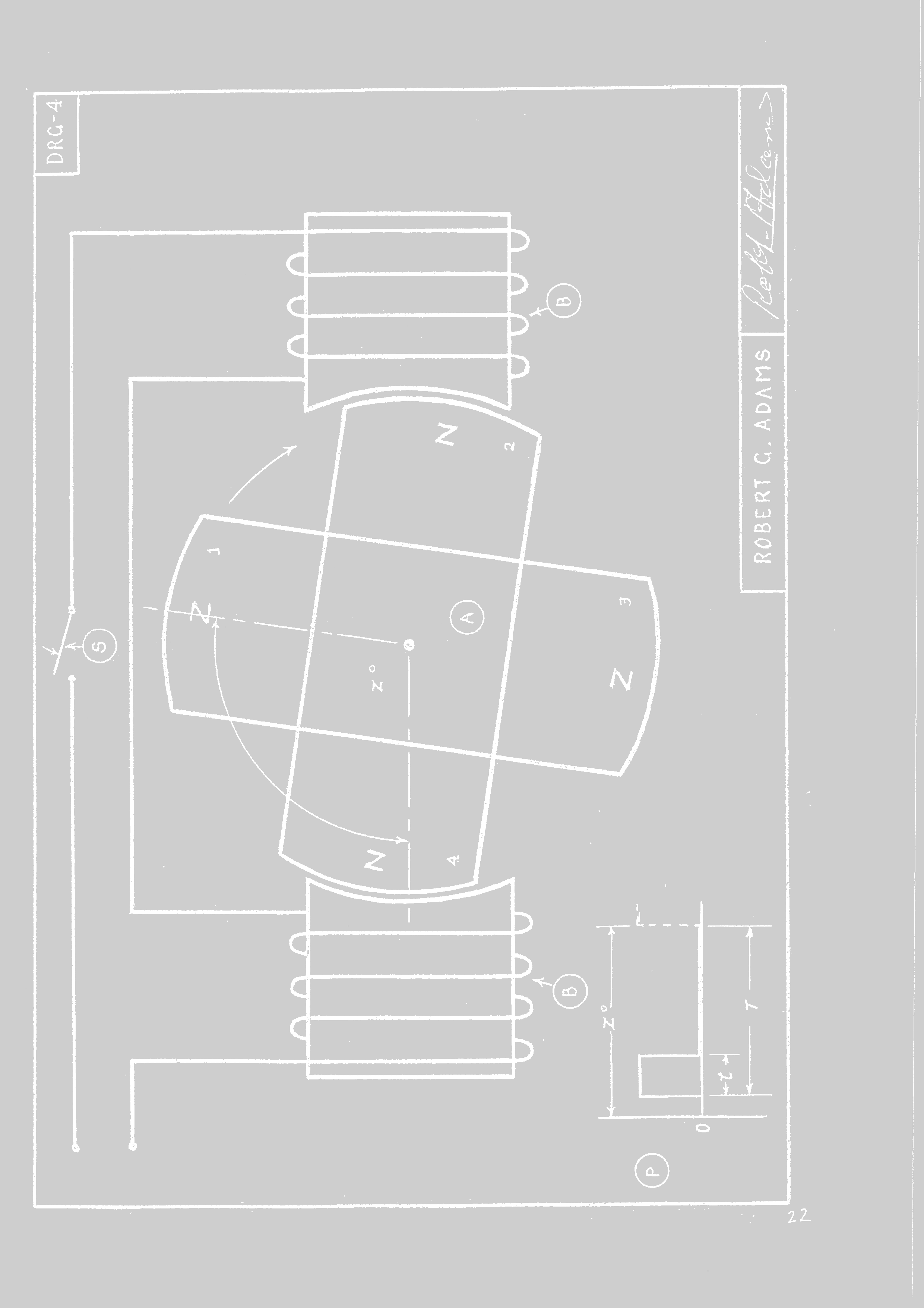
Mr Adams has drawn broad magnets and drive cores in his sheets. Electric engineers know the importance of the cross-sectional area for a powerful magnetic force. 

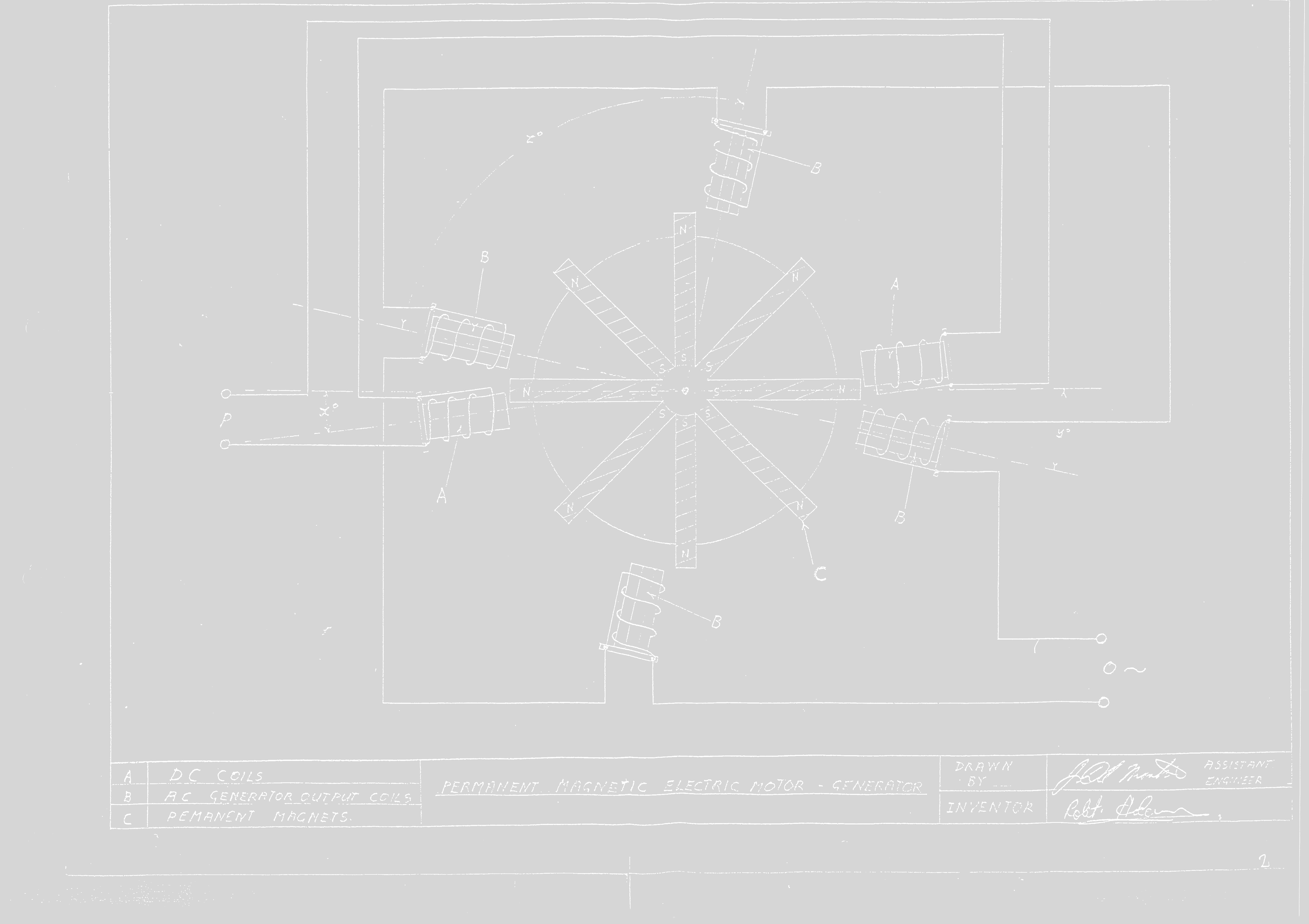
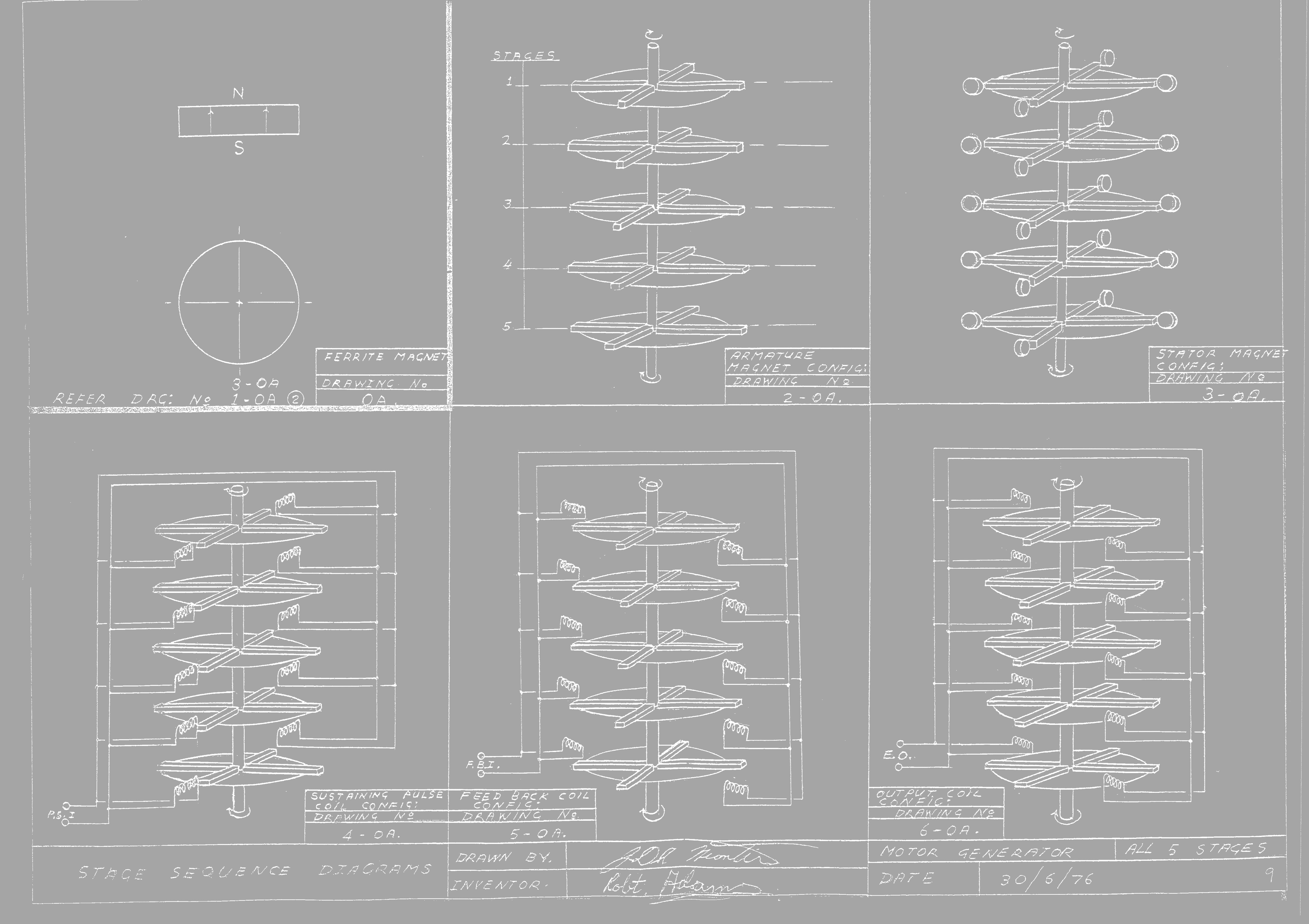
In contrast the drawings made by John Martin seems to be more conceptual to show different types of configurations and connections. 

We can examine different conventional machines, motors and generators both, and see clearly that the area of the magnetic components is directly related to the power ratings. This does not mean that only broad and wide magnetic components will give a significant performance, but the total of the cross-sectional area will be always proportional to the maximal power rating. But of course, also many small coils and magnets will add up to make a powerful motor or generator. In this drawing by the way we can see that short disc-shaped ferrite magnets are used: 

It becomes clear that Robert Adams has designed a wide variety of different machines with different shapes of magnets and coils. So, we cannot expect a recipe or design rule which applies to all of them. 

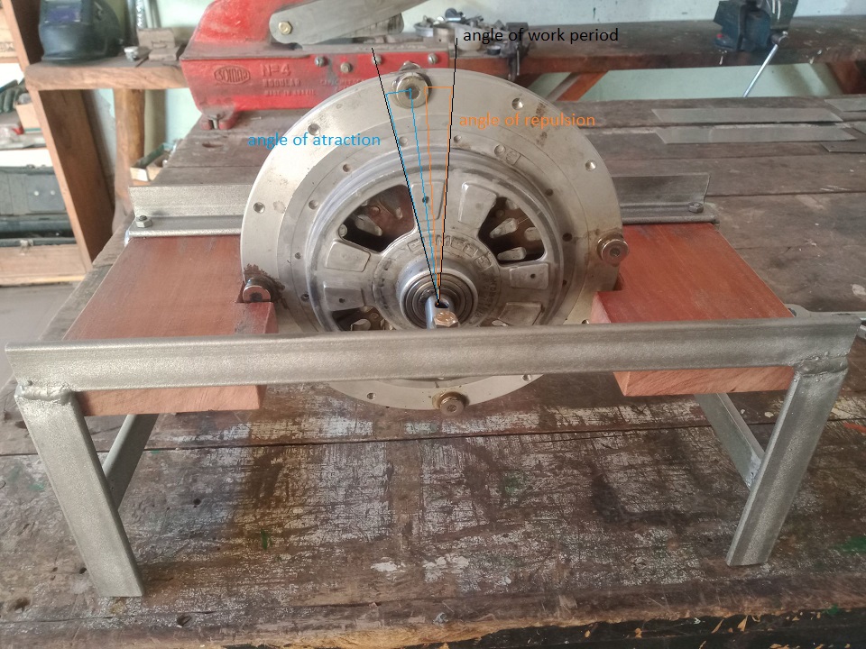
Coming back to the switching parameters, it is also clear that these have to be chosen according to the geometric layout of the motor. As I have shown in the YT video of the magnetic force between rotor and stator, there is a very defined position of the magnet, when the attraction becomes strongest. In this position the drive coil has to be magnetized at its maximum. But how many degrees of the rotation this position occupies, depends on the size and shape of magnets and cores. The same is true for the angle where the effective work of the motor is performed.

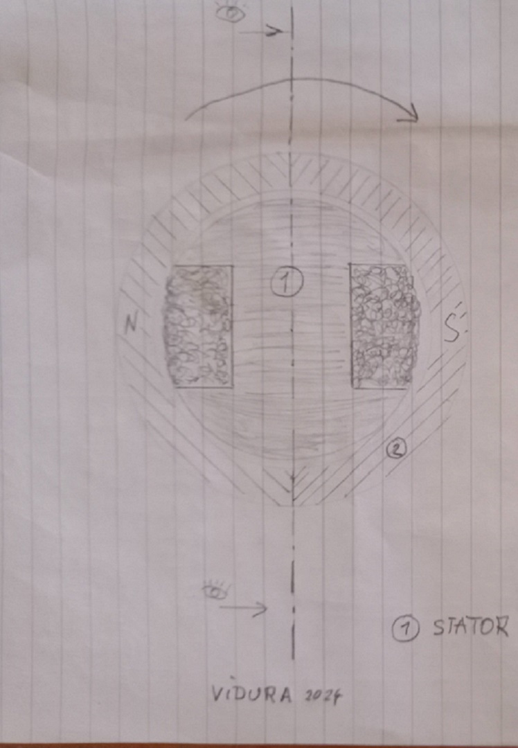
For example, in the drawings below:

In the position of the first drawing the attractive force is still small, the pulse is initialized. The exact position varies depending on the inductance of the coil and the delay of magnetization of the core material.

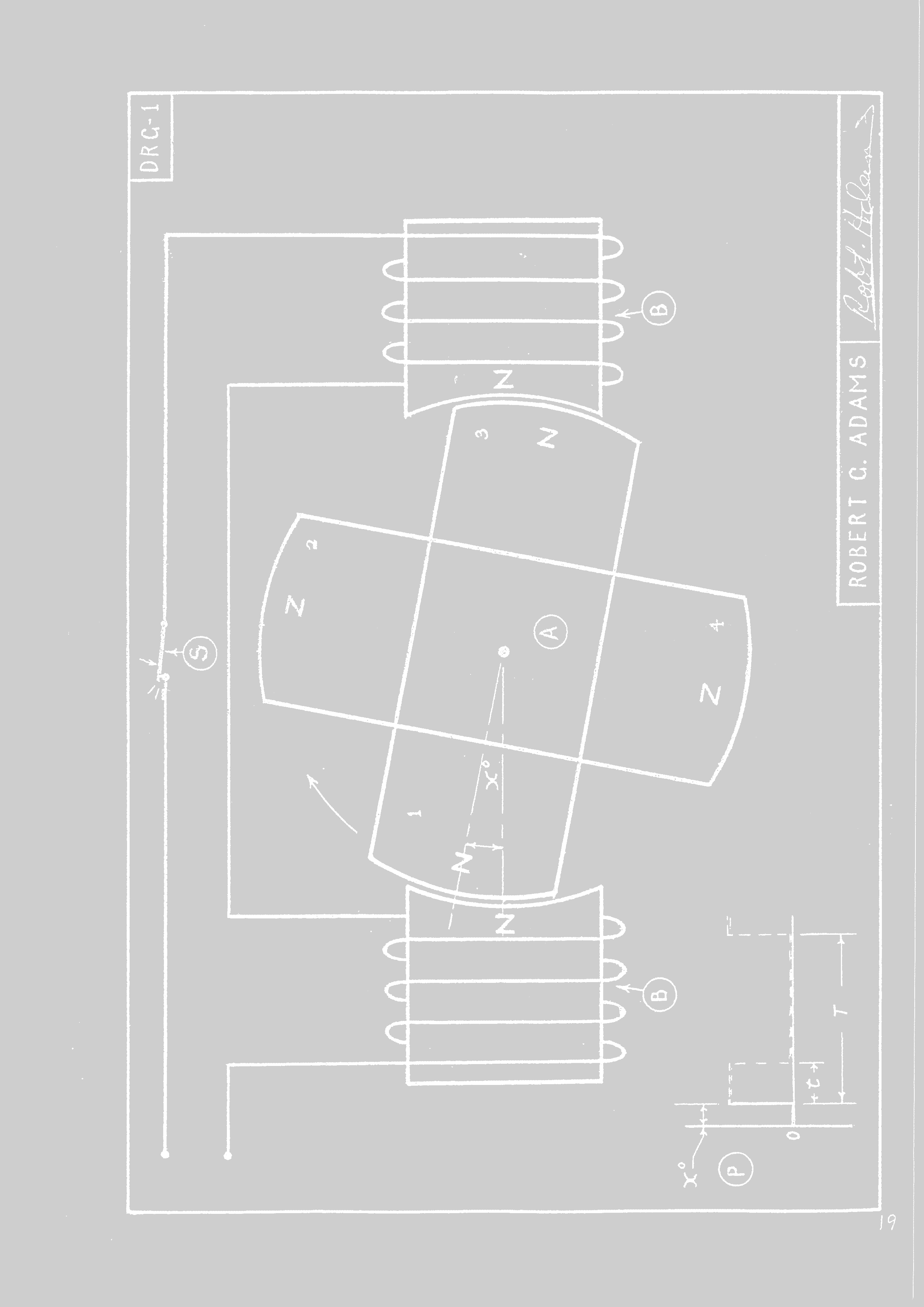
In the next drawing the relative position of the rotor is near the maximum of the magnetic attraction force and the pulse is turned off. Again, there is some delay in the demagnetization of the core material, which still is repelling the overlapped magnet.

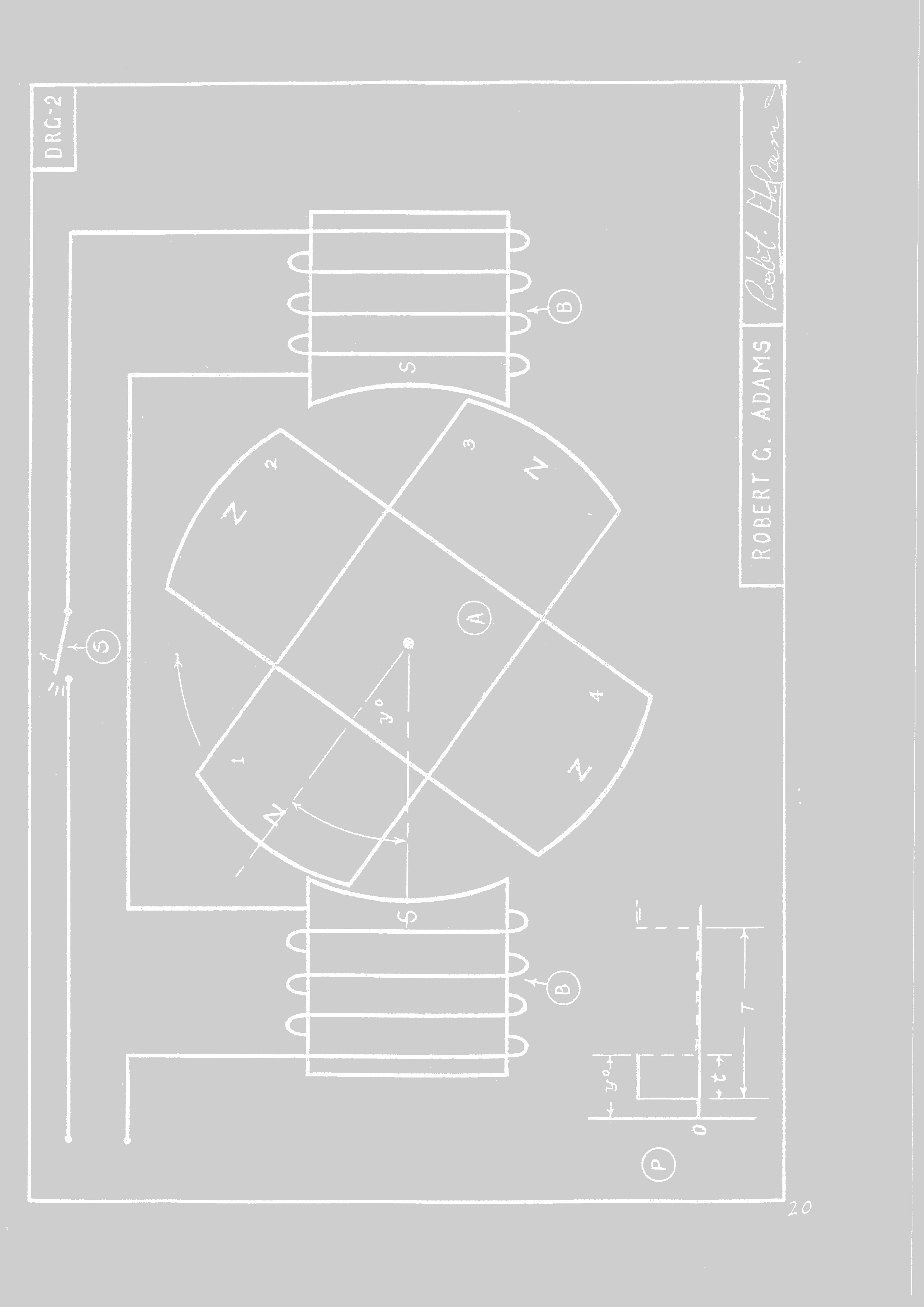
When the rotor moves a bit further, the cores demagnetized completely, and the next approaching magnet will attract the core from the other side, here the second part of the work period starts. This part is for free, as no electrical energy needs to be applied.

Therefore, a motor of such a geometric shape similar as in this drawing would perform work almost continuously during the whole rotation, but would require a pulse of less than 50% DTC to drive it at full power. And with appropriate switching techniques around 80% of the input power could be recovered for recycling.  I think these are excellent conditions for an OU machine.

Vidura

Vidura posted this 5 days ago

For more clarity below I have drawn the approximate working period in my test motor:

It can be estimated that the work period would cover approximately 25% of the angle between the magnets, leaving 75% of the possible angle unused. This relationship would significantly improve by mounting a magnet pair in each hole.

Vidura

Close