Control circuit for Fighter ZPM

  • 1.9K Views
  • Last Post 17 hours ago
YoElMiCrO posted this 01 March 2025

Hi everyone.

@ Fighter.

This weekend I took up your ZPM to see how
the frequency/duty variation can be controlled
based on the load applied to it.
That way I think it will be easier for more people to replicate it.
I'll keep you posted.

Below are the STL files I used for the reels.

YoElMiCrO.

Attached Files

Order By: Standard | Newest | Votes
YoElMiCrO posted this 01 March 2025

Hi everyone.

@ Fighter.

This weekend I took up your ZPM to see how
the frequency/duty variation can be controlled
based on the load applied to it.
That way I think it will be easier for more people to replicate it.
I'll keep you posted.

Below are the STL files I used for the reels.

YoElMiCrO.

Attached Files

YoElMiCrO posted this 03 March 2025

Hi everyone.

@ Fighter.

Well this week I did a few experiments
with your ZPM in an attempt to understand what the control circuit has to
do to keep the phenomenon active in ZPM while the load is varied.
For now I will use a PIC12F1572 for this task,
the response time is somewhat slow, about 200 mS, but
we will see how to improve it little by little and if it is worth it.

YoElMiCrO.

Fighter posted this 03 March 2025

Hi Yoel,

Sorry for the delayed reply, I saw your post but I was on the road and I wanted to allocate proper time for my reply.

Because of they way they're built every ZPM have its own characteristics therefore its own specific optimal frequency and duty-cycle.

Manually finding the optimal frequency and duty-cycle is time consuming especially when the load on ZPM's output is changed and the process of finding a new optimal frequency and duty-cycle needs to be repeated.

So yes, your circuit which can auto-adjust ZPM's frequency and duty-cycle depending on the load is more than welcomed especially for new builders which when they build their own ZPM are not familiar with device's behavior and find it confusing.

I added your post to my Favorites list so I can build the circuit when I'll have some time for my current experiments and new experiments.

Two questions about your tests with ZPM:

  1. From your photo it seems to be powered by a battery, not by a DC source, do i understand this correctly ?
  2. Is there any ground connection in the circuit ?
  3. When you have some time can you post a schematic on how the entire circuit looks like (connections between ZPM, the control circuit and the battery) ?

Your ZPM configuration seems similar to Atti's ZPM replication, if I remember well he also used a battery and the ground connection was not required even if, as Atti specified, a ground connections increased his ZPM's efficiency.

Thank you for sharing your circuit and experiments !

Regards,

Fighter

"If you want to find the secrets of the universe, think in terms of energy, frequency and vibration."
Nikola Tesla
YoElMiCrO posted this 6 days ago

Hello everyone.

@Fighter.

First, sorry for the delay, things are complicated these days…
Yes, I perform all the tests using batteries as power sources.
No, I don't use any ground wires.
The circuit is exactly the one you published!
This week I took some time to continue the analysis.
It's worth noting that I managed to replicate it with TOROID #43.
With 9V batteries in series, it's impossible to make it work.
The problem is that initially you'll need a very large current,
while the supply voltage is constant. Let me explain…
Given the large value of the inductance in parallel with the load,
we can ignore it initially, and the circuit would function as a shopper.

Since the DTC is constant at 25% and the load is a 55W @ 12V bulb…
RL = Vbulb^2 / Pbulb = 12^2 / 55 = 144 / 55 = 2.62 Ohms.
The power consumed during the Ton cycle will be…
Pinst = Pload(Nominal) / DTC = 55 / 0.25 = 220 Watts.
And the voltage required at the power supply will be…
Edc = SQR(Pinst * RL) = SQR(220 / 2.62) = 24Vdc.
Considering the conduction losses of the switch plus those associated
with all the components, it makes sense to increase the supply by 1Vdc, giving 25Vdc.
Now let's calculate the initial current required…
Idc(Initial) = Edc / RL = 25 / 2.62 = 9.5Adc.
This current is independent of the frequency used since the DTC is constant.
Only the ZPM depends on the latter, and it is such that the core is magnetized to a certain value.
The ZPM definitely has over-unity, and you can see this by adding the areas after Ton.
The ZPM assembly functions as a resonant circuit and uses the mass of the core
along with magnetic inertia as a gain mechanism.
What I still haven't been able to explain is why the power displayed by the power supply appears to drop so much.

YoElMiCrO.

Jagau posted this 6 days ago

Hello Yoelmicro

What I still haven't been able to explain is why the power displayed by the power supply appears to drop so much.

Question for you my friend.

Do the indicators on a digital DC power supply indicate instantaneous power or average power over time?

Maybe the power return produced this drop instantly but not over time?

Jagau

Fighter posted this 6 days ago

Hi Yoel,

No worries about the delay, the enough time for experimenting is what all of us are missing in this period.

For now I'm working on my DSE experiment and building that customized capacitor is very time consuming.

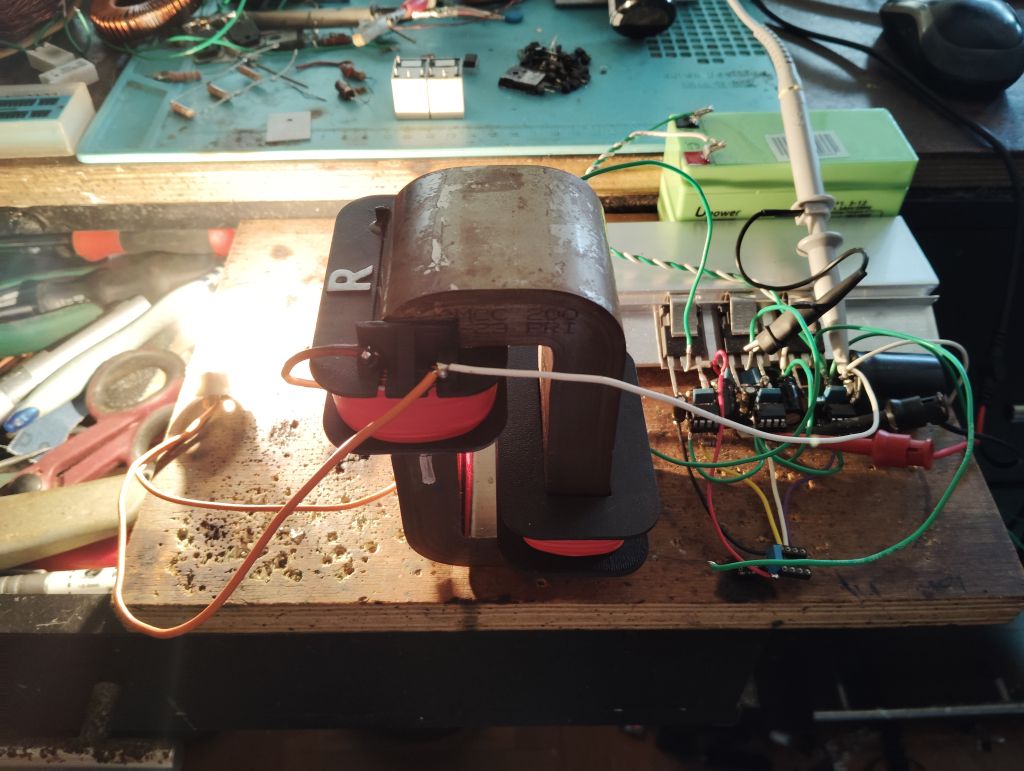
But at some point I will return and continue the ZPM enhancement work and I'll use the new DC source and the high-frequency filter I bought as I specified here.

Altought I'm not sure how introducing that filter in the circuit will work (with its coils and capacitors) because from my previous experiments I noticed ZPM doesn't really like to have additional components (especially coils) introduced in its circuit. But if it works and those filters will do their job theoretically the DC source should be protected against that high-frequency waves produced and used by ZPM.

So you're saying that the initial pulse need larger current (9.5 amperes) while making sure the voltage still remains at 25V ? Yes, batteries are not able to maintain voltage constant, were you able to make it work using batteries ?

Also, another question: that current (9.5 amperes) is required only for the initial pulses (when ZPM starts working) or it's required for every pulse (while the ZPM is working already) ?

I'm thinking that maybe after ZPM starts working that current is extracted from ZPM's gaining mechanism and the DC source doesn't need to provide it anymore ?

Thank you for explainign ZPM's gaining mechanism.

I'm also still convinced that ZPM is overunity, that didn't changed in my mind over time.

Fighter

"If you want to find the secrets of the universe, think in terms of energy, frequency and vibration."
Nikola Tesla
YoElMiCrO posted this 6 days ago

Hello everyone.
@Jagau.

All power supplies display average power.
For example...
With a square wave, the average is calculated by integrating time only,
while in a sinusoidal wave, it is necessary to integrate twice.
Definitely, in the ZPM waveform, there is no mechanism that
generates a current in the opposite direction to the power supply.
That's why I still don't understand the mechanism. What is certain is that
the sum of the areas after Ton are larger and therefore over-unity!

This image is with a TOROID #43. The oscilloscope probe is
in parallel with the load and the inductor, as in the ZPM circuit.
If you look closely, after Ton, there are three areas: two in the flyback direction
and one in the forward direction. The ratio between the sum of the areas and the area of ​​Ton
is greater than 1; that's a fact!

YoElMiCrO.


Jagau posted this 6 days ago

Sorry but my standard power supply when in CV mode delivers constant voltage and a varying current, 

resulting in an instantaneous power (P=VI); that can change depending on the load.

I don't see how it can calculate average power like an oscilloscope would.

Jagau

YoElMiCrO posted this 6 days ago

Hello everyone.
@Jagau.

This way, the power supplies "see" the load connected
to them if the load has a connection/disconnection time.

YoElMiCrO.

AlteredUnity posted this 6 days ago

This may be relevant to what Fighter was getting at. To get the avg power these supplies as YoElMiCrO shown, takes the Vavg * Iavg. Meaning through measurement of current over a shunt resistor and amplifier, these continuous analog signals are representing instantaneous values. These values are filtered or averaged usually through an integrator-based control loop. Then a slow ADC will read the conditioned, filtered, and averaged values over time, and send to the display.

Any returned power since our supplies cannot sink power(which now i know why my supply is given more voltage then it is set to put out in one configuration ive shown somewhere in my replication), is only pushed to the output capacitors, the supply then only needs source a bit less power on the next cycle..

My PS doesnt specify measurement method, I may be wrong on the operation, but from while trying to find the limits of my PS, that is what I've read for most PS.

Jagau posted this 6 days ago

Hi Yoelmicro

The digital displays of a power supply see this as you say, but only in continuous DC. On that point, I agree, and the formulas are correct.

But with PWM, as in the ZPM example here, the reading isn't good; even a good-quality Fluke meter won't display the correct value. This is mostly a job for an oscilloscope; power supply multimeters aren't fast enough, especially with high-frequency PWM.

When working with pulsed current or PWM, you cannot simply multiply voltage and current to obtain power; here, the RMS values ​​must be used. But there's a caveat that the RMS part will include current running both ways. This is fine for dimensioning and calculating power for resistors, as you did, but when the circuit has an inductor or capacitor that returns some current each cycle, the above power calculations will fail!, like in ZPM.

Jagau

Close