Control circuit for Fighter ZPM

  • 3.1K Views
  • Last Post 08 September 2025
YoElMiCrO posted this 01 March 2025

Hi everyone.

@ Fighter.

This weekend I took up your ZPM to see how
the frequency/duty variation can be controlled
based on the load applied to it.
That way I think it will be easier for more people to replicate it.
I'll keep you posted.

Below are the STL files I used for the reels.

YoElMiCrO.

Attached Files

YoElMiCrO posted this 28 August 2025

Hello everyone. @Jagau.

Let's talk about energy... Imagine a 25% duty at 1Hz applied to the same circuit. The energy supplied by the DC source will be... (Vrl^2/Rl)Ton=E(Supply). (100/10)0.25=2.5J/s. Since the frequency is 1Hz, the power will be 2.5W, just that. DC sources don't know what they're feeding; they only know the energy that came out of them over time.

YoElMiCrO.

Jagau posted this 28 August 2025

In a pure 10-ohm resistor with a constant voltage of 10 volts flowing through it, the current will be 1 ampere. As in your example, the DTC is 25%, so the average power, which when using a pure ohmic resistor, will also be equal to the instantaneous power, therefore 2.5 watts. This is verified by your formulas, and it is normal in this case of power with a pulsed circuit using a pure resistor for the power to be constant.

Since we are talking about the ZPM and we are using components that store and release energy (coils), in this case, the instantaneous power will be different from the average power because the current through the inductor increases from 0 amperes. The initial instantaneous power will therefore be from 0 watts to a maximum of 4.33 watts, as in the following example.
Experiment already performed on the ZPM with this figure: Yellow PWM pulse , Green Current probe

On the oscilloscope, we can see that the current increases linearly with a starting voltage of 0 amperes.

The PS tells us that 4.33 watts comes out of it making an average of 4.33 Watts, yet at the beginning we have 0 amps and therefore 0 watts of power, it interprets a maximum power as an average power. The PS therefore makes an average power of 24 x .18 = 4.33 watts it does not know that this power is transmitted only 38.2% of the time starting at 0 watts and therefore considers the average at 4.33 watts random and not precise reading, as would a DDM connected to the input.

The power is not constant and we cannot trust the display of the DDM of the PS, they do not have the same formulas to use for the calculation of power and a DDM of PS cannot do that in addition to the frequency used. With an oscilloscope the average power displayed will be different, because it can do Pave = Vrms x Irms x DTC     

The ZPM is beyond unity for sure.

Jagau

YoElMiCrO posted this 30 August 2025

Hello everyone.
This is the method I use to calculate
the minimum power the power supply should provide
to a circuit like the Fighter ZPM.
I say minimum because I assume all components
are ideal, meaning lossless.
Here's the image.

YoElMiCrO.

baerndorfer posted this 01 September 2025

it is always fascinating when i see how we can explain things if we use math and logic. the problem is, that sometimes it did not work as we think it should work.
what do i mean by that...
in the examples above we think, that current is always the same in its shape. but there are curcuits out there, which can produce current, that looks different on high side than on low side. when someone opens the door and led negative energy in, then every component in the circuit acts like an amplifier for this type of energy. you will see that, when you have huge voltage drop on tiny resistors (i have 5V voltage drop on 10mOhm Shunt for example) without any heat involved. all circuits on this website can do such things if the conditions is set.

high side of coil current can be 'ordinary DC' while on low-side we have huge components of reactive energy.

so in my opinion the best way to test such circuits is a battery which can be monitored over time.

have a nice day!

Jagau posted this 02 September 2025

I agree with what you say, Beardorfer; everything can only be explained by math and logic.

In an electronic circuit, certain phenomena cannot be explained by logic alone. That's why we're all here, and the goal of our research is to try to replicate these phenomena, which are still difficult to explain.
An example:

We can see in this formula that the energy consumed by the coil in the circuit is added to the energy actually consumed by the resistive part of the coil.

On the other hand, an inductor does not consume energy; it stores it, and when an inductor releases energy at off time, it returns the stored energy back into the circuit as a temporary current source, thereby reducing the net consumption of energy from the external power source for that specific task.

This is why the energy from the power supply cannot and is not the same as the energy actually consumed in the circuit when using coils; wwe must calculate the difference between the energy actually consumed and the energy returned as in the case of the ZPM.

Jagau

Jagau posted this 05 September 2025

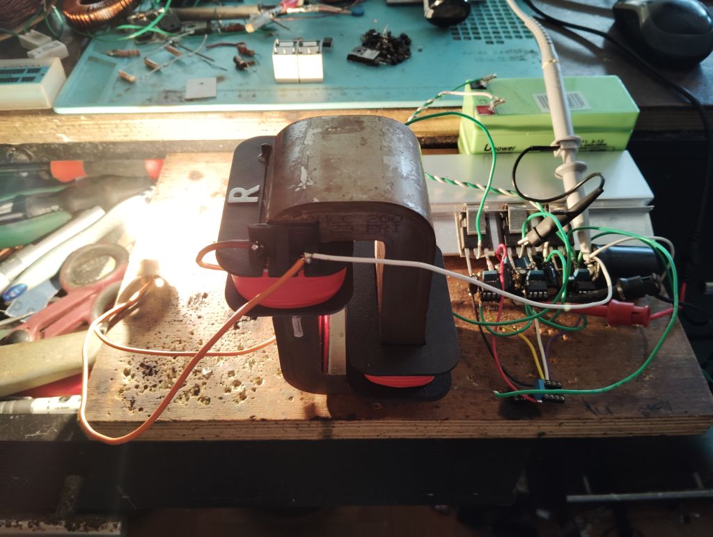
I built a 1.6 MHz coil, and using an online calculator, we got reactance of 10 ohms versus a frequency of 1 kHz.

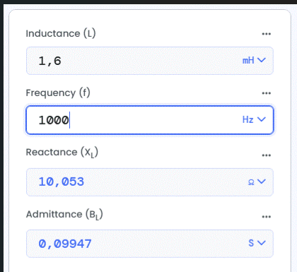
Xl = 2pi fl = 2x 3.1416 x 1000 x 1.6 mh = 10.053 ohms

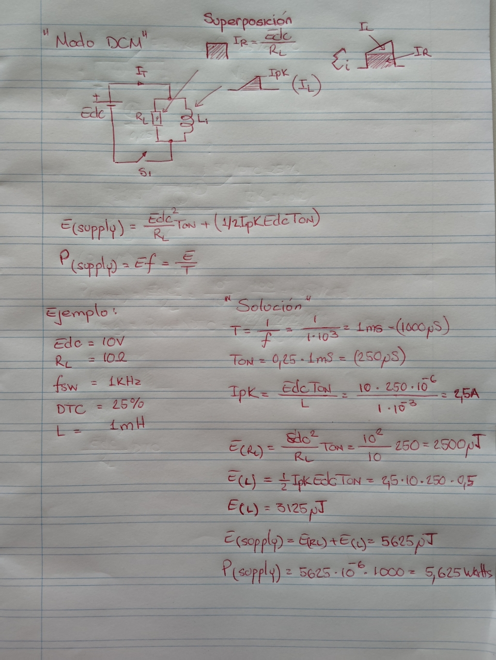
On the PS, with an output of 10 volts and a DTC of 25%, we get this:

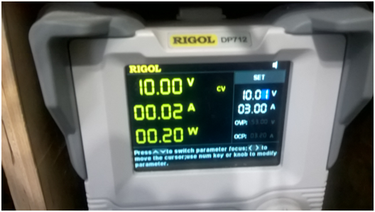
20 mA and 200 milliwatts output on the PS

We can see the same current consumption as the PS on the Fluke and a photo of the FG with the 1 kHz info and 25% DTC

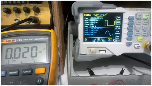
Same amperage as on the PS 20 mA

On the oscilloscope software, we can see an analysis of the circuit in question; the voltage is measured with a differential probe and the current with a Tek current probe.

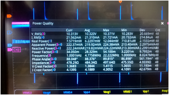
Since the circuit uses an inductor with an impedance of approximately 10 ohms, the reactive power of the inductor corresponds to that of the software, i.e., 219 milliwatts, and on the PS, 200 milliwatts. The scope is always more accurate than a PS.

Quote from Bearndorfer:

high side of coil current can be 'ordinary DC' while on low-side we have huge components of reactive energy.


The actual average power of the circuit is therefore 6.3 milliwatts, even if the PS gives 200 milliwatts.

This example can help us understand our circuit for future analysis, which is why I say that the ZPM is beyond unity.

Jagau

Jagau posted this 06 September 2025

I really appreciate all the formulas that Yoelmicro has given us, he is a very knowledgeable person in this field and these formulas are always accurate and I use them regularly in my research.

The goal here is to learn together and try to understand these bizarre phenomena that surround us in order to understand them in relation to existing formulas and to reproduce them with an explanation that is not easy to explain for us.

Think about it carefully:
Electromagnetic phenomena cannot be explained without the participation of the vacuum. Even if you remove all the particles from a region of space, even if there is no longer a single electron, not a single atom, the electromagnetic field will continue to exist in the vacuum.

I'm sorry to have interfered with your thread

"Control circuit for Fighter ZPM"

and hope to have the chance to read the following of your thread.

Jagau

YoElMiCrO posted this 08 September 2025

Hello everyone.

@Jagau.

Can you make the circuit you tested with and
where are the oscilloscope probes?
The power supply shows 20mA @ 10Vdc.
On the other hand, the inductance is 1.6mH while
the frequency is 1KHz @ 25% DTC.
This tells me the following...
di/dt=Edc/L=10/1.6*10-3=6250A/s.
Ton=T*DTC=250uS.
Ipk=(di/dt)*Ton=1.5625A
P(Supply)=0.5*Ipk*Edc*DTC=1.953Watts.
The image of your power supply shows 0,2Watts.
The only thing I can think of is that you have a mechanism
to return the magnetic energy to the supply source,
and what this shows is the power loss.
If that were the case...
COP = [(P(Supply) - Loss) * 100] / P(Supply) = [(1.953 - 0.2) * 100 / 1.953] = 89.7%.

It's fine to change the topic within the thread as long as
it's related to the thread. In this case, it's related to everything we do.
In fact, we all gain knowledge as we interact, so we'll all get to Rome sooner or later!

YoElMiCrO.

Close