I'm starting this thread to present my miscellaneous ideas and experiments.
Costinbuc's Ideas and Experiments
- 2.7K Views
- Last Post 24 March 2024
any suggestion will be highly appreciated - an results will be shared freely
- Liked by
-

-

-
-

- and 1 others
Hi Costinbuc
How to measure E field and H field
https://www.youtube.com/watch?v=ctynv2klT6Q
you can do that too with a TinySA mini spectrum analyser and make your own probe, here
https://www.youtube.com/watch?v=PSbsAl_lVro
and it work very well and making your own probe with RG174 as per instruction in the video.
Jagau
What we consider to be empty space is merely a manifestation of unawakened matter. N.T.
Quoting:costinbuc
The big problem is that I can not measure E-field outside of core
About measuring it see Jagau's advice above.
Also to just check if that electric field is present around the core this method could work and is very simple:
Would be interesting to see what happens if there were several stryfoam balls suspended from threads hanging over that coil. Bet they would be dancing everwhere.
Styrofoam should be affected by an electric field like we know it's affected by static electricity.
That's how I'm planning to check when I'll have time to resume my Aharonov-Bohm Effect experiment.
Fighter
| "If you want to find the secrets of the universe, think in terms of energy, frequency and vibration." | ||
| Nikola Tesla | ||
Hello,
I need to add a correction here: initially the field around the core is not an electric field (E), it's an uncurled magnetic vector potential (Ā); we need to convert it to an electric field (E) by perturbing it sending very short and sharp pulses within some small input coils. After that we will obtain an electric field (E) around the core which we can detect (as discussed before) and which can be collected by the bigger output coils.
I added more details in my personal note here.
Regards,
Fighter
| "If you want to find the secrets of the universe, think in terms of energy, frequency and vibration." | ||
| Nikola Tesla | ||
Hello all.
I have tested one air core alone to see how it's working on square wave form at frequency 1 kHz.
I can tell that I do not understand what is showing the osciloscope. Power Source is 5.4 V - 4 x AA accumulators.
- Liked by
-

-
-

-

- and 1 others
Hello Costinbuc
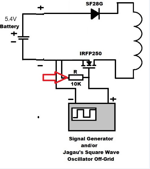
The gate of your Mosfet cannot discharge correctly, place a 10 Khoms between the gate and the ground of your mosfet then you will see a change on your scope.
Jagau
What we consider to be empty space is merely a manifestation of unawakened matter. N.T.
I am totally confused about this. Power Source 5.4 V DC ;
After this Jantzen coil 0.94mH, 0.5 ohm rezistance osciloscope shows Vmax +19V - Vmin fluctuating .......
Hello Costinbuc,
Jagau is refering to this resistor placed between the gate and the ground of the MOSFET:
You can find more details in my post here, more specific in the left-side lower part of this image (see the resistor labeled as RGS):
Regards,
Fighter
| "If you want to find the secrets of the universe, think in terms of energy, frequency and vibration." | ||
| Nikola Tesla | ||
Hi Fighter, I placed the resistor exactly in that position
No one online at the moment
-
-

-
-

-


