Resonance energy and Don Smith Proof of Concept

  • 942 Views
  • Last Post 5 hours ago
Jagau posted this 3 weeks ago

To avoid overloading Fughter's thread, I've created another thread on the Don Smith system.

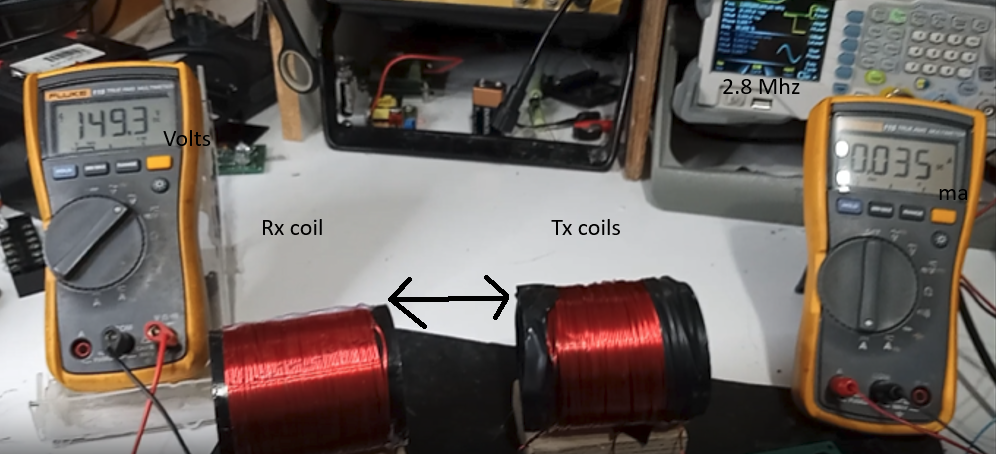
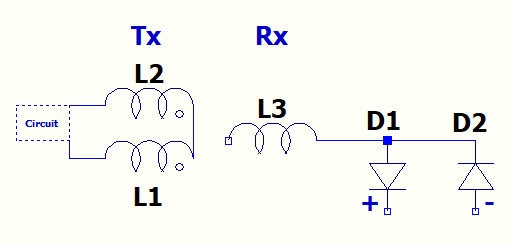
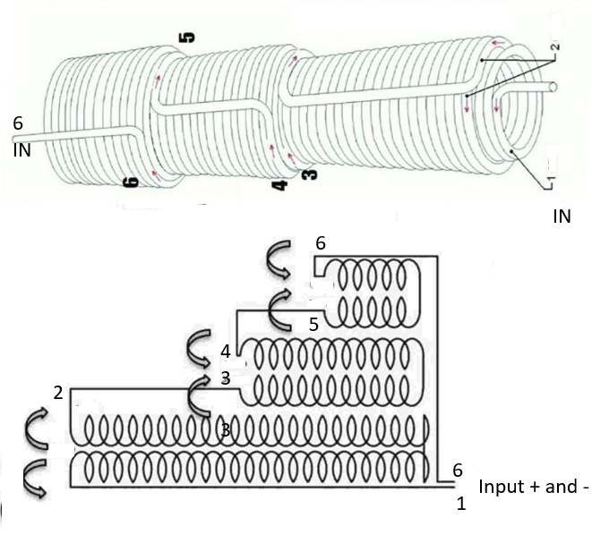
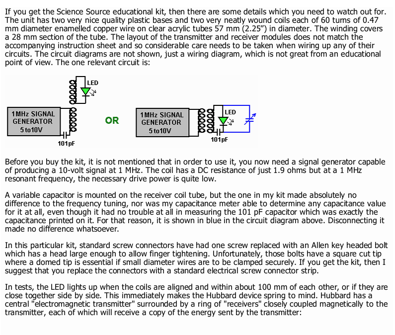
The first experiment will be to verify, with two 60-turn 2.25-inch PVC coils, what one reel can transmit to the other without a transformer effect, using different coil placements like the one he gave as an example often described in his books. Just a transmitter and a receiver coil.

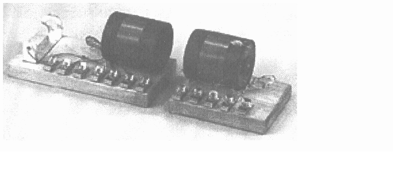
I will build these two coils and will do a practical demonstration.

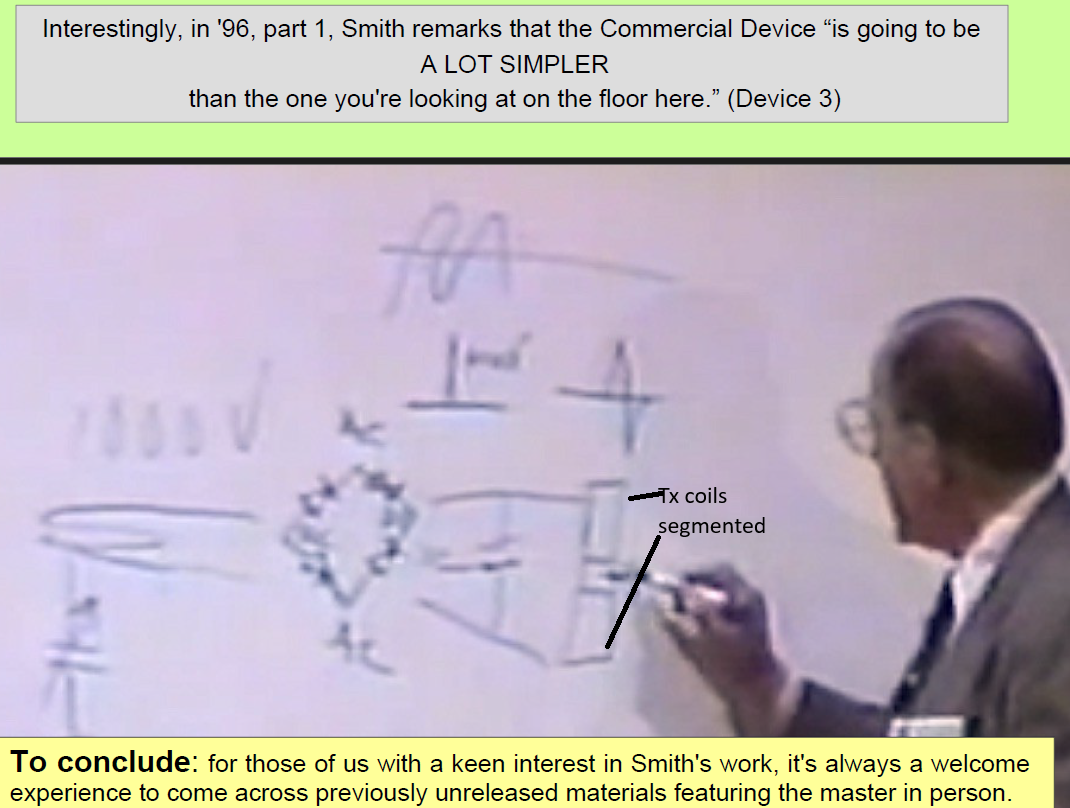
The text of this experiment we find in D.S book:

Jagau

What we consider to be empty space is merely a manifestation of unawakened matter. N.T.

Inception posted this 2 days ago

By seeing these type coils, one can imagine their repurposing, toward energy production. The tight-loose configuration appears to purify resonance, which improves gain. It also helps with directing magnetic fields, such as what Jagau is experiencing. 

I've worked briefly with directed energy production in the early 70s. I was fascinated with gas and ruby lasers. The goal was to focus and magnify device output, without destroying the equipment, and yourself.

There are many ways to focus magnetic fields, using magnets, inductors, and even mu-metals. If we apply some of these methods to our energy devices, along with signal source controls to induce greater primary resonance ... efficient primary to secondary couplings ... we will overcome the unity gain boundary, and then shift to constraining methods, so our devices will not runaway and destroy themselves. The spark gap inherently offered that contraint, but they have short lives.

Note: The reason I acquired those two assembles was strictly for the coil forms themselves. The result was a brief education on inductor configurations. 

Inception

Jagau posted this 2 days ago

Very good, Inception. You're going to have a lot of fun with your new coils!

As you can see in my last video in page 1, with just a few volts, the difference is almost 40 times greater.

Just imagine with 1kV or even 4kV, like DS used, and a pulse under 10ns.

T. Kapanadze and E.V. Gray used a second flux amplifier, while D.S. used only one. All three inventors have several things in common, the main one being grounding, that's where the amperes come from.

Remember that the circuit itself will never produce overunity; making the environment work for us, yes, overunity is possible.

MAGNETIC FLUX, MAGNETIC FLUX remenber.

Coils use a loosely coupled design, where the primary and secondary coils are physically separated to create low mutual inductance and typically a very low  coupling coefficient. This separation enables high-voltage at resonance, allowing energy to transfer effciently between circuits as per design of Tesla.

I have started experimenting with higher voltages and shorter pulses, and the result is astonishing.

Jagau

What we consider to be empty space is merely a manifestation of unawakened matter. N.T.

andy2 posted this 2 days ago

Hi Jagau

Do I understand corectly that your TX coil has the same identical on top of it? Same number of turns for the same resonance, but not connected to anything?

A.

Jagau posted this 2 days ago

Hello Andy

The TX coil has two windings, one on top of the other, separated by tape (segmented), creating a second segment separate from the first.  Loosely coupled design, with coils physically separated create low mutual inductance and low  coupling coefficient.

The first is CW (close-wound) and the second is CCW (counter close-wound), joined in the center. Both coils are therefore in series with opposite phases, and yes, they have the same number of turns: 60, producing a slightly longer coil (wider diameter) for the second one as suggested by D.S.

The circuit for TX coil is pulsed with a Nmosfet at 2.69 MHz  (resonant frequency) and a 12 VDC battery with adjustable voltage of approximately 4.5 VDC at 35 milliamps.

The position of the coils as demonstrated increases the inductance and a large magnetic flux is produced in the block wall located at the series junction of the two coils.

I hope that answers your question? Don't hesitate to ask!

In this proof of concept, the goal was to demonstrate the effect of external GROUNDING ROD and that magnetic flux is the important factor to consider.

The next two experiments will demonstrate that the load does not affect the input and what power can be obtained by controlling what comes from the mass, as D.S. said, the dam control.

Jagau

What we consider to be empty space is merely a manifestation of unawakened matter. N.T.

andy2 posted this 2 days ago

Thank you for explanation.

I also didnt notice that you have RX coil one side open in the video.

Thank you a lot and I am looking forward for your next posts.

A.

Jagau posted this 2 days ago

Before 1994, the information that D.S. was more precise than it is today after 1994.
If you look closely at the attached photo from 1996, D.S. demonstrated that you have to pulse the two coils at 1kV, which I call the Tx, then collect on the third with an open system.

The first part, up to the capacitor, is only for producing 1KV pulsed DC, from there, it doubles the voltage with the help of the diode bridge and re-amplifies it again by double tesla coils, in my case about 40 to 50 times as you saw in my second video.

This is what I demonstrate in my experiments, but at low voltage.

You see where he has his pencil, the dam, that will be the next experiment.

Jagau

What we consider to be empty space is merely a manifestation of unawakened matter. N.T.

andy2 posted this 2 days ago

For me is also interesting, that:

  • you can get such enhancement by using "two" coils as transmitter 
  • by adding grounding to the receiver coil you get so huge voltage

A.

Jagau posted this yesterday

Just a very clear clue from another inventor, T. Kapanadze, who shows how to make the primary coil.

You'll notice that the voltage is amplified three times by three sets of pair segmented  anti-phase coils.

EV Gray, Kapanadze and Don Smith have several things in common.

The main part is barely revealed in the three inventors' account. What is the role of the dam and how does it work? We know very well that the surplus does not come from the circuit itself but from its environment!

I confess I've never tried pulsed 3 pairs of antiphase coils, only one pair at a time; it would be a great experiment to see the result!

Jagau

What we consider to be empty space is merely a manifestation of unawakened matter. N.T.

Fernando posted this 17 hours ago

Hello Jagau, very nice experiments and the way to explaind very clear, looking forward to see your progress in this intriguing system. Thanks for shearing. Something  in the next video can be helpfull.

?si=V4g5Qw1fJUDOBWVh

Jagau posted this 7 hours ago

Thanks Fernando, I'll take a look at that.


So, having reached this point, we have 150 volts of RF radio frequency and we can do something with that, as D.S. said.


Next we need to build a dam that will control the charges coming from the ground! by placing a variable capacitor between the two Tesla coils.

That will be the next experiment.


A little more theory:
To achieve a gain greater than unity, the input must be low (thin primary, high impedance) and the secondary output (low impedance) must supply a high current. This is the secret of Don's circuits. But Don never revealed this trick. Those who saw Don's schematics with a thick primary and a thin secondary encountered output power problems: gain less than unity, or equal gain. I call this a reverse Tesla coil: the primary becomes the secondary and the secondary becomes the primary. Kapanadse had this idea, and you can see that his coil is based on Don's circuit.


Jagau


What we consider to be empty space is merely a manifestation of unawakened matter. N.T.

Close