I transferred my thread on Ferrite at Work here to BeyondUnity.org
Ferrite at Work
- 7.1K Views
- Last Post 03 September 2024
Hello,
As I promised to Jagau the import of this thread is now complete.
It has 141 posts and for each it needed direct access to our database, image importing, links, text formatting and a lot of attention to details. Plus a lot of translations from Russian to English where Google Translate was very imprecise sometimes... 🙂
As this process cannot be automated, it can be done only manually and it's very time consuming.
But it's worth the effort, in time we gonna get all our data here to home where it belongs because it's the work and the property of the members of our team.
Jagau requested here for his threads to be removed from the old aboveunity site but of course that cuckoo-boy from the old site can't do that because without the work done and shared there by our team he would have nothing on his site. 😉
As the device shared in this thread is overunity it's now officially tagged with the "Beyond-Unity" tag and I will add it to the section "Our Beyond-Unity Devices" on the right-side of our site.
Jagau, if you find any (possible) errors I've made during the import please feel free to edit/correct them.
The thread is officially yours now.
Regards,
Fighter
| "If you want to find the secrets of the universe, think in terms of energy, frequency and vibration." | ||
| Nikola Tesla | ||
- Liked by
-

-

-

-

- and 1 others
WOW what a great job Fighter, it's like a Christmas present, thank you a thousand times.
Researchers can also follow this thread and its evolution
on the site here of BeyondUnity.org
Jagau
- Liked by
-
-

-

-

- and 1 others
You're welcome ! 🙂
This is your research and belongs to our home where you are and where our entire team is.
Fighter
| "If you want to find the secrets of the universe, think in terms of energy, frequency and vibration." | ||
| Nikola Tesla | ||
- Liked by
-

-

-

-

- and 1 others
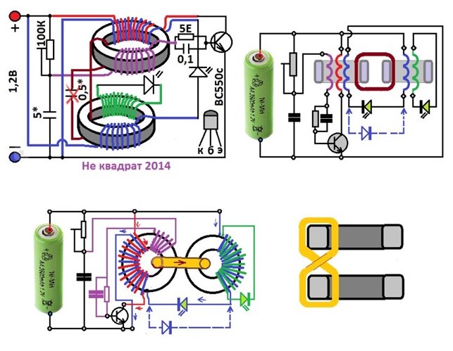
Greetings. How should I understand the purpose of this circuit? Does it only increase the efficiency and the LED will last much longer at the same brightness than without the circuit? Or theoretically the LED would be on forever and it is only limited by battery life (degradation of material due to recharging)? I have built the circuit and I am testing it (latest version with 5R and 100n C in the base). So far I have not reached the point where the voltage on the battery starts to increase (AA NiMH). I noticed that you mostly use white led (the one connecting the windings on both toroids, name it Led1). With white Led1, I was not able to achieve the desired waveform at 1.2V supply voltage. When powered by 1.5V Zn-C batteries, it worked with white. In order to make it work at 1.2V, I had to use Led1 with a lower loss (red). I noticed that achieving the desired waveform depends a lot on the supply voltage and with it on the used Led1. And also on the position of both toroids relative to each other. I will deliver screens later..
We had a lot of fun doing this circuit and good memories.
You probably guessed that the goal was longevity of your rechargeable battery, do not use standard battery.
But to get there you have to reach this oscillation point on your oscilloscope.
I would say that most of those who tried the circuit succeeded and
a circuit well done by Rakarsky to follow:
Good experimentation
Jagau
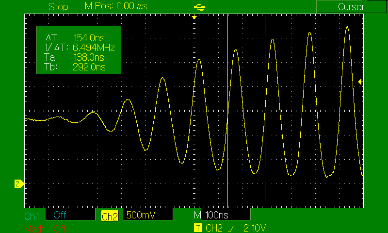
Hi, here is the waveform I managed to achieve with a 1.2V NiMH battery.
Battery voltage 1,318V (very slowly decreasing), current 2.7mA (minimum current to achieve this waveform). Measured on the collector-
Here current 7mA
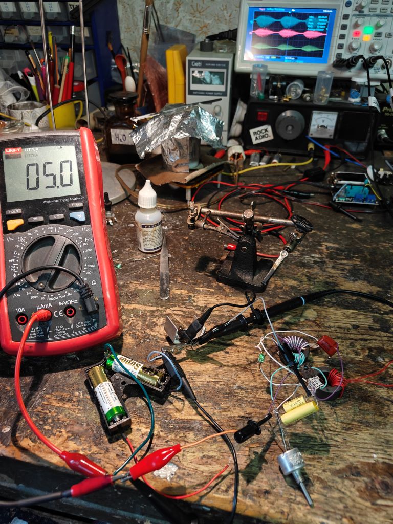
Setup (here it still didn't work with 1,2V battery)-
I had to leave the capacitor on that one thread between ferrites, without it it didn't work. I had to put the ferrites on top of each other (flat). I got it running at 1,32V thanks to the red LED1 and its lower Uf. I chose 14 LEDs with Uf 1.59V-1.96V + white 2.93V and tried which Uf will work. It worked only in the range of 1.75-1.80V . The closest +- values were 1.73V and 1.85V. So a pretty narrow range for functioning. The sine is kinda clean compared to yours though. I don't know if that's correct. The battery wasn't charging after all. Ferrites unknown, I tested them with a VNA and they work at high frequencies(as I'm typing this now I realize I didn't measure the AL constant at all). The transistor is a BD139. LED1 was lit a bit, LED2 not at all.
Nice replication abitanoying it's very good.
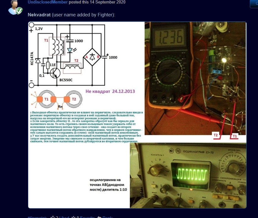
Nekvadrat, the author and the first one who designed and published this circuit, had found something very interesting.
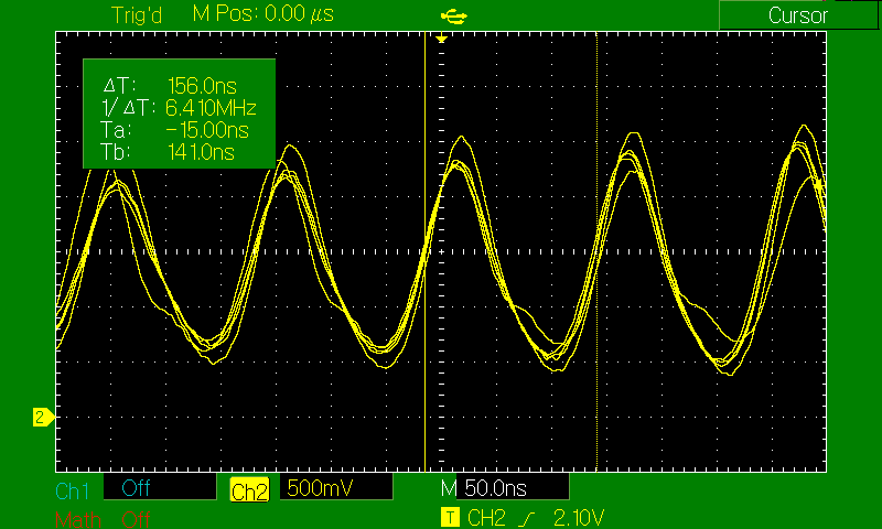
As you can see on the following picture the pulse train of 150 khz and in each of these pulse trains, a second frequency appears, that of 13.8Mhz occurred.
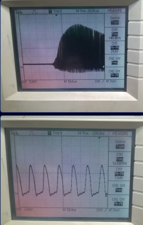
Tesla (150K) and Dr. Stiffler (13.8hz) told us that at these frequencies have to be monitored particularly with regard to the ZPE zero point energy. That's what I did.
The author (Nekvadrat) had advised us to take rechargeable batteries 1.2 volts because at these precise frequencies something magical happens. The battery recharges at the same time as it is consumed, which greatly extends the longevity of the battery, that was the goal of this experiment.
Another recommendation from the author, regarding the BD139, if you can, try instead a 2N2222 , is rf amplifiers up to 300 MHZ, the bd139 is below 190mhz.
You are on the right track. Nice work
Jagau
Oh, so it's about frequency, I missed that.. OK that means my ferrites have a higher AL than the author's. So half capacitance should solve it, now there is 1.8uF (and frequency about 6.5MHz). As for the transistor, why do you think 150MHz is not enough? We are dealing with a frequency of 13.8MHz. Those photos are yours, right? What current was it drawing in your case?
- Liked by
-

-

-

-
- and 1 others
In fact the author suggested a BC550 with a Current Gain Bandwidth of 300Mhz, the equivalent 2n2222 has the same characteristics and the harmonics can develop better. Just try maybe also a 2n2363 which has even more present characteristics. up to you to see, only experimentation will tell, the authors do not always say everything in their approach.
For myself these double critical frequencies with pulse train are important, you have to get there by adjusting the parameters.
A schematic that Nekvadrat sent to me with BC550 and battery voltage.
Jagau
- Liked by
-

-

-
-

- and 1 others
I'm making a reminder , about the measurements with a DDM for those who have forgotten or the new ones who are joining us.
The question is, can a DMM Measuring maximum and minimum voltage/current in PWM ?
This is mostly a job for an oscilloscope, multimeters are not fast enough. If you can control the PWM it is easiest to measure DC voltage at highest and lowest PWM setting. The min/max function on multimeteres usual requires about 0.3s or 300ms to measure a value, this means it cannot be used even at 10Hz. Some meters has a "peak" function, this may be able to measure 1ms or even 0.1ms peaks.
From the above table it is fairly obvious that even the peak function is too slow when the PWM frequency gets much above 100Hz.
For power measurement. When working with pulsed current or PWM you cannot just multiply voltage and current to get power, here the RMS (or rather DC+AC) values can be useful.
Example: 0V to 10V with 10% duty cycle will delivering 0A at 0V and 1A 10V. It is easy to calculate that it will deliver 10 watt when (Voltage x Current -> 10 x 1) on and with 10% duty cycle the power is 1 Watt. But using the DC values that is 1V (10% of 10V) and 0.1A (10% of 1) gives 0.1 Watt, i.e. very wrong. What about DC+AC values, that is 3.16V and 0.316A and gives the correct 1 Watt.
But there is a caveat on that, the RMS part will include current running both ways at input, this is fine for dimensioning the cable and calculating power for resistors but when the circuit has an inductor or capacitor (reactive circuit) that returns some current each cycle.
In fact, at input if you rely on the power measurement display of your power supply as would reading a DDM, in the presence of reactive circuit, the above power calculations will fail! and for power output measurement, phase angle between current and voltage must be in calculation, this is where an oscilloscope excels. with their new power management software.
When measuring on PWM it is important to know what the result must be used for, average is useful for some measurement and AC+DC is required for other The bandwidth on multimeters is for AC measurements including DC+AC, but DC measurement usual works at much higher frequencies. For meters without DC+AC it can be calculated this way: DC+AC = sqrt(sqr(DC)+sqr(AC), DC+AC is based on the true RMS value of the AC (I have not seen AC+DC on a NON TRU RMS METER.
ALMOST EVERY RESEARCHER ON THE FORUM HERE KNOW THIS, I HAVE ALREADY POSTED THIS ARTICLE BEFORE AND KNOW HOW TO TAKE MEASUREMENTS WITH A DDM.
Jagau
- Liked by
-
-

-

-

- and 2 others


