Micro generator

  • 3.4K Views
  • Last Post 3 weeks ago
Jagau posted this 09 May 2022

Energy Harvesting with Electro Magnetic Micro Generator

Energy Harvesting (EH) from human or environmental sources has proven to be an effective alternative or complement for battery charging or other uses.

 As light, thermal, mechanical and RF are major sources in EH and among them, mechanical energy from wind, waves, vibrations, etc. is commonly existed in our daily life.

In this new thread the energy will be harvested by using micro generators. This research project addresses the development of a unique EH circuit capable of fulfilling our needs.

more to come

Spark2

Jagau posted this 08 November 2023

Nice improvement Getza well done
Jagau

Jagau posted this 11 December 2023

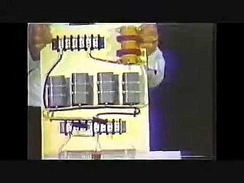
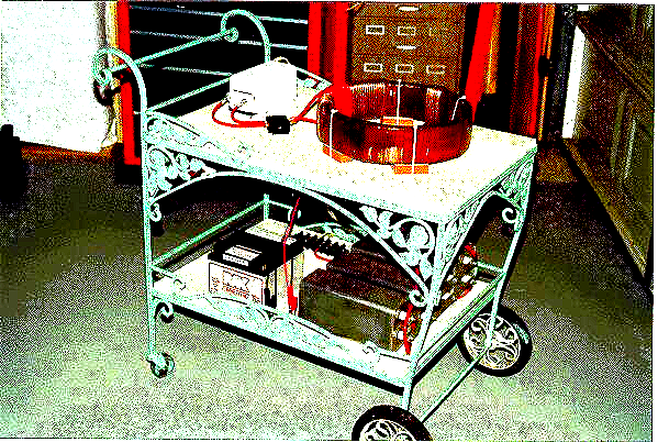
Don't forget that the micro generator also works very well exactly as Nicolas Tesla built and patented it,

like this:

If you are in the presence of or near a source of radiant energy you can collect it with this device.

Like Fighter did with ZPM or the Don Smith effect.

All I did was the circuit controller, Nicolas Tesla invented the device which seems so simple, but !!

But not that much.


Jagau

worldcup posted this 3 weeks ago

Quoting:Getza

My mod to this lovely shem. I put a second Led in negative line, both Led blink with  with equal brightness.

https://youtube.com/shorts/wOMYR6vUosE?feature=share

@Getza, Yours working till date ? any improvisation so far ?

Regards

Jagau posted this 3 weeks ago

Great job, World Cup.
Have a lot of fun with this circuit.
You can even do it between two people with sweaty fingers, takes a little longer to activate but it works.

I did this at a family gathering and people thought I was a magician, which I'm not.

Jagau

HansKammler posted this 3 weeks ago

amazing Circuit ! Thank you. As I thing about your schematic 2 things come to mind:
Henry Moray (Rexresearch) about get rid of earth connection (during test in Airplane with the RER):

"[p. 188] The years slipped by and from time to time Henry and I would discuss his notes and go over the drawings. He spent most of his time [ca. 1950] working on what he called the "counter-balance" to eliminate the need for an antenna..."

and the joseph Newman:
" the energy comes from the copper atoms (weight of Copper is linear to the output power)"

addendum:

“Counterbalance” – what does that mean?

By “counterbalance,” Moray meant a kind of artificial earth/counterweight that eliminates the need for an actual ground wire.

There is nothing mystical about this in radio technology:

A long wire or rod antenna only works if there is a reference potential → normally earth.

Instead of real earth, an electrical counterweight can be created: a second capacitance or conductor that closes the antenna system.

Example: A capacitive resonant circuit or a balanced antenna design (dipole, loop).

This way, the circuit is “closed” and does not require a separate ground connection.


That was standard practice at the time. An “earth connection” was not necessarily “physical earth” in today's sense, but often a ‘counterweight’ that electrically “complemented” the antenna.


Why does this work?

HF does not see “0 Ω earth,” but impedances. A wire lying freely above the ground has a capacitance C to earth (typically several 10–100 pF depending on length/height). Together with the antenna impedance, a displacement current flows back.What does this look like in practice?

Mechanics: A piece of wire (or metal foil/plate) at the ground point of the device. The other end of the wire remains free (insulated), simply lying on the floor/in the room → capacitive coupling.

Position: Spread out as much as possible (along the floor, window sill, radiator without electrical contact), not wound up.


Length:

Rule of thumb: 0.05...0.25 λ helps significantly.If space is limited: as long as practicable; even 1–3 m can make a difference with shortwave. 

Height/area: The closer to the ground and the larger the area, the higher the capacity → better counterweight.


Jagau posted this 3 weeks ago

Hello.
Thank you for your comments, and I encourage anyone who wants to discuss this.

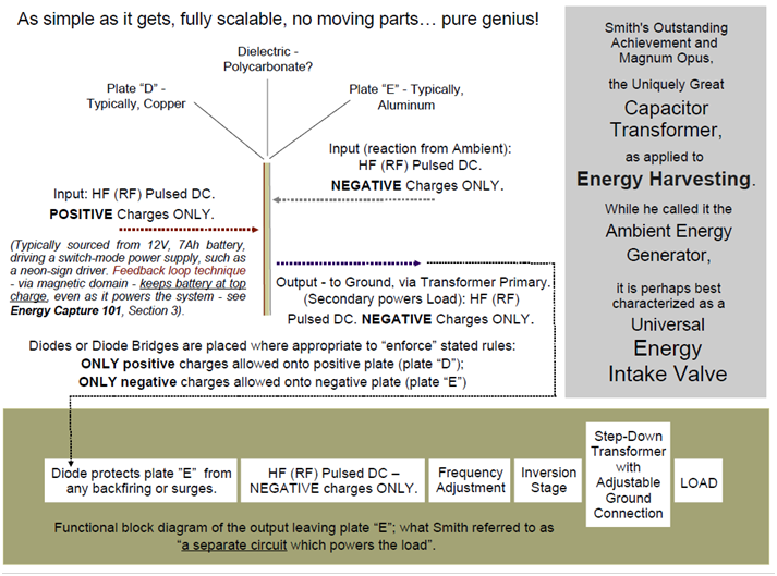
The idea to build this circuit came to me after seeing this image in a Don Smith book some time ago.

As we know, energy is everywhere in the universe. Don Smith often talked about it in his books.

As you can see in D.S.'s image, the right side of the capacitor was directly connected to ground, giving it a negative charge.

After some experimentation, and knowing that with a diode bridge, the positive side could be was also charged directly onto the capacitor from another ground, which maintained the + and - terminals.

In short, this circuit has an input ground and an output ground, creating two very high-impedance circuits. Everything happens at the junctions of the bridge diodes, and of course, a small transistor is used to switch the voltage to the LED when it reaches a certain point.

Jagau

baerndorfer posted this 3 weeks ago

the only thing i would be interested is the step-down transformer mate

because you only can understand don smith, if you knew all this stuff in great detail.

HansKammler posted this 3 weeks ago

so as i understand this: a capaitor with copper dielectrica and aluminium plates loaded via diodes corected path. and one side is the "earth ground" and the other a HV puls.

as the positiv plate sucks elektrons from the negative plate aka pumping from earth one by one and storage in the grenzschicht of conductor and dieelektrika. since a spark gap fires to push the power from cap to a load.

I would choose kaptan for the dieelektrika because of high K Value.

OK I think I understand.

@baerndorfer:
have you a image of the output transformer / inverter ?
i only see on DS images only oil filled capacitors .... (brazllian tabletop and EarthSystem V3)

HansKammler posted this 3 weeks ago

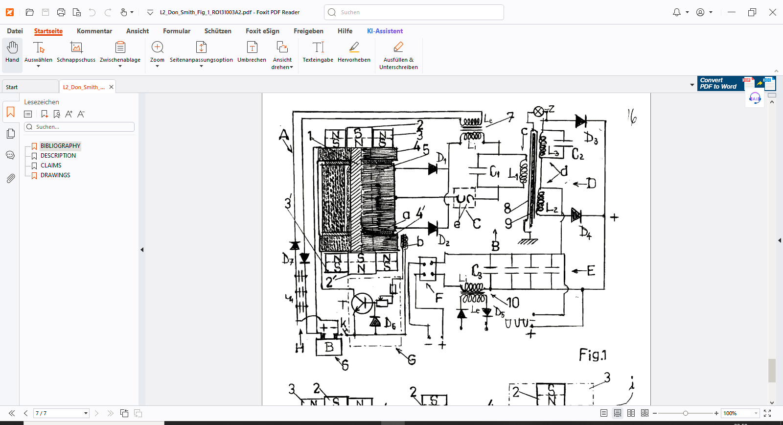
another solution is found in an patent which merges DonSmith and Kapadnadse from Romania: the output transformer is #10 and the starter battery is #B

Attached Files

  • Liked by
  • Inception
  • Fighter
Jagau posted this 3 weeks ago

I think we're a bit off track here.
I just explained how the idea came to me.
It's a micro-generator with two high-impedance inputs to ground or air ground too, that doesn't sense voltage from ground but from the surrounding environment. Sorry if I didn't explain well.


Jagau

Close