Non-Inductive Coil Experiment

  • 1.6K Views
  • Last Post 6 days ago
bri77 posted this 3 weeks ago

I have tried to replicate the Non-Inductive Coil Experiment. I get similar effects to what Tinker (neale) gets.


For the wave forms, the saw tooth drops down really fast, so it's for like 70%+ of the time. When I increase the frequency from 3k or so to 12-15k the wave form becomes similar to what's shown in video 7.


I do not have something to measure current right now.

Using amcc0320 Proterial

Primary - cw 14awg ,1.628mm. Wound on top of poc1.

Poc1 - cw 20awg, .813mm

Poc2 - ccw 20awg, 0.813

The input are all 5v and the amp shown are the amps on the x-tronic px-70 power supply (linear power supply). The pwm generator is FeelTech fy6300. It is set to 10v ampl and 5v offs square wave (This is to get 0v to 10v square wave pulse). The mosfet used is (IRFP4227PBFXKMA1): https://www.mouser.com/datasheet/2/196/Infineon_IRFI4227_DS_v01_02_EN-1227486.pdf. This has a 21mOhm RdsOn. The signal output from the pwm generator is connected directly to the gate of the mosfet. The primary + is connected directly to the power px-70 power supply. The primary - is connected to the drain of the mosfet. I have a 25v 470uF low impedance capacitor conncted to the priamry + coil and the gnd of the power supply.

One 12v 5w bulb on poc1. Another 12v 5w bulb put on poc2.

I tried to get the peak voltage the same for both poc1, poc2 with the following coils:


22mm wide
primary 7 turns (single layer) (around 13mm wide on top of poc1 about)
poc1 60 (3 layers) turns 21.8mH 1.105uF 0.6ohms
poc2 60 (3 layers) turns 21.8mh 1.138uf 0.6ohms
2800hz 10% 5v .235a poc1: 17.29v peak, 2.33v avg  poc2: 17.28v peak, 1.84v avg


22mm wide
primary 7 turns (mutilple layers) (around, 8mm wide on top of poc1 about. I should try to get it closer to 1/4th which is 5.5mm.)
poc1 60 (3 layers) turns 21.8mH
poc2 60 (3 layers) turns 21.8mH
2800hz 10% 5v .238a poc1: 17.77v peak, 2.33v avg  poc2: 17.77v peak, 1.74v avg


53mm wide
primary 7 turns
poc1 55 (1 layer) turns 18.28mH
poc2 55 (1 layer) turns 18.33mH
3700hz 10% 5v .195a poc1: 15.4v peak, 1.86v avg  poc2: 15.5v peak, 1.57v avg


22mm wide
primary 9 turns
poc1 180 (9 layers) turns 192.5mH
poc2 180 (9 layers) turns 194.0mH
300hz 5% 5v .345a  poc1: 18.85v peak, 1.98v avg  poc2: 17.36v peak, 1.61v avg

All of these experiments, the sawtooth ended really early (70%+ flat line) before the next pulse.

The lights were mostly the same brightness.

With the 180 turns on the poc, the frequency had to drop really low (300hz), for  the peak voltage to be about the same, and the sawtooth ends really fast, so there's a lot of flat time. Also the shorter width coils the frequency had to be lower, for the peak voltage to be the same.


When I raise the frequency, the saw tooth wave form is closer to what tinker and video 7 shows, but poc1 output would increase (4-5v average), and poc2 output would be (200-500mv average).

I am not sure what can be done to get a better sawtooth waveform (going all the way to the next pulse start) and having both poc1 and poc2 output to be close to each other.

I've tried winding primary over both pocs with different number of winds on each poc. I also tried winding the primary over one poc and then switching the direction of the wind before winding over the second poc. The wave forms weren't what was shown in video 7, but I did see in one of the cases both coil would have the same wave sawtooth waveform (like what you get on poc1, where it dips down when pwm rise then spikes up when the pwm falls.) I'm not sure if this is the way to get both pocs to have the same output, but it used a lot more power. One of the combinations of the diodes the output was about the same, the other combinations one was 2x more than the other.

I've tried all 4 combinations of diode direction on both pocs also.


The main thing I want to try and get is to have both pocs have the same output and a good sawtooth waveform (not ending early before next pwm pulse). I might of missed something, but the width of the coil if it's smaller, the magnetic field strength is supposed to increase, which is supposed to increase voltage /current?, but it didn't really increase that much for me with the 60turns (22mm wide, 3 layers) and the 55turns winds (55mm wide, 1 layer). I've tried higher voltages also, but it did not seem to give the result that I wanted (I forgot what the results were).  I'm not sure if it's my switching system, but the square wave seemed ok, not super clean.  I'll try building the "Quadratron" to see if it makes much of a difference. I think the things that I have left to try is the quadatron, change power supply?, shorten length of wires. Get a better 1/4th width ratio of the primary coil over the secondary. Maybe something is wrong with my core? or try a nanocrystalline core instead of amorphous?


I'll probably try replicating fighter's zpm also, once I understand things more.  I've destroyed a 12v sff power supply and a few mosfets so far. I stopped destroying mosfets now, and using the 470uf capacitor the power supply does not go into protection mode? (Clicks and resets back to 5v) anymore and I can increase voltage.

YoElMiCrO posted this 3 weeks ago

Hello everyone.

@Jagau.

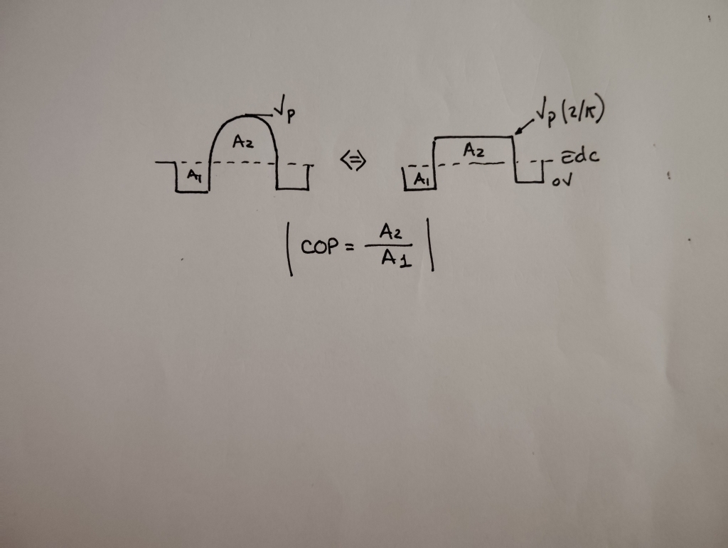
When the magnetization cycle has a sinusoidal component,
it's useful to ask the question...
What is the square area that fills half a sinusoidal cycle?
Since the base of the square must be equal to the sinusoidal,
the peak sine value times 0.637 will be the equivalent amplitude in the square wave.
So, you've just converted a half-sine function into a square wave response, that's all.
Here's an image...

YoElMiCrO.

Jagau posted this 3 weeks ago

Hy Yoelmicro

When the magnetization cycle has a sinusoidal component

As an example in the case of an undamped sinusoidal oscillation produced on secondary side by a DC square pulse on the primary.

Yes, it is good to question the result, both formula are equivalent as in your image.

I see what you mean now.

My confusion was that Bri's oscilloscope images didn't have a sinusoidal component. Thanks for the explanation.

Jagau

Jagau posted this 2 weeks ago

Hello Bri77

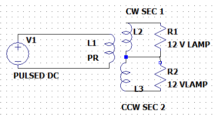
Is it your coils configuration ??

[   poc1   ] 

|               |

->|--[load]--


[   poc2   ] 

|               |

->|--[load]--

The loads are the 12v bulbs.

R1 and R2 are loads 12v bulbs on each secondary coil, and you want to pulse the primary at low voltage.

Tell me if that's LTspice schenatic is correct for you?

Jagau

bri77 posted this 2 weeks ago

Hi Jagau,


Poc1 and Poc2 are not connected together. It's connected like what chris has in his video 7. Primary wound on top of poc 1.

The ->| symbol in the ascii art is the diode.


AlteredUnity posted this 2 weeks ago

Bri77, unless you are using differential probes, your coils are essentially connected together through the ground of scope. May as well get rid of any potential differences or imbalances that may occur, and connect both gnd wires of the secondary together, and each gnd lead from probe to that point.

bri77 posted this 2 weeks ago

Replying To: AlteredUnity

Thank you,

I connected the ground for the pocs and the gnd of the input power together now.

Also, I think I have the following: primary oppossing poc2, poc2 opposiing poc1, poc1 assisting primary.

For the right hand rule, you curl your fingers from + to - for the primary coil (direction of current flow) for the N direction of the magnetic field, but for the pocs you curl your finger from - to + if hte diode is like this: poc ---- >| -- +, the other end of the poc would be -. The >| is hte diode in that example.

So you curl your fingers in the direction of the current flow to see which way N is pointing for the magnetic field, if I understand correctly.


AlteredUnity posted this 2 weeks ago

I think you misunderstood what I was saying, the primary should stay isolated.

Only 1 side of each secondary should be tied together(this is where you connnect gnd FROM SCOPE).

The other side of the secondary1 and 2 goto their own diode through their own load - then to centertap where Secondary1 and 2 are tied together. ĹLike in Jagau's LTSpice model.)

At least from the configuration you are explaining which he shorts 1 of the secondaries through a diode(no load)- to gnd(OF SCOPE) where the center tap of the seconaries connect.

Jagau posted this 2 weeks ago

Hello Bri77


Make a real electrical diagram, we'll better understand what you want. We can't create a schematic like you do with words; it's unclear to us and difficult for you to express, so please make an electronic diagram of your experience.

So as Alteredunity says you will see where to place your probes in the circuit.

Jagau

AlteredUnity posted this 2 weeks ago

Bri: you're always welcome to participate in any experiment on here, but post here again you may get banned there. We are all about progress, I understood what you're trying to achieve and you have the right hand rule correct. On Schematic's you will see the dot next to the top of the primary(or where ever current enters), for the output/secondary the dot represent where current or voltage is coming out. Check my thread on his site, you will see different working arrangements. Or Jagau's, or Fighter's, or Atti's, or YoElMiCrO's, or CD'S, baerndorfer, wisiti, you know all the disgraced people that he is talking about.

The best example you can follow from that site is Adam's Experiments. He truly explains how to find where and how/why to put diodes on the output. He truly excelled quickly compared to my thread, even surpassed Chris's "shared" experiments.

We only asked for diagram and setup info so your not reading repeated pages of the same crap.

Your lack of response or hand drawn diagram prevented any help. But we here(excluding me) where the top contributors to his site, most any experiment worth looking at you can find the author here, and are gladly here to help.

I sent you a private message, with some instructions and working experiments. Though got no response.

GL on your projects, it looks like you've done a lot of setting up different configurations, so your interested and probably overwhelmed, but our replies arent copy and pasted, we care for everyone's safety so want to make sure we get a full assessment of your setup before giving a half-ass response.(like when you connected secondary gnd to primary).

bri77 posted this 2 weeks ago

Thank you AlteredUnity, YoElMiCrO, Jagau,

I should probably lean more about EE first. I'm self taught in all of this stuff. Only really started recently (besides doing some RC heli stuff like 15 or so years ago, dealing with esc, fets, motors). Only bought a oscilloscope really (and learning how to use it now) recently when I wanted to check to see if my built Rife machine (followed some simple schematic for this) was acutally getting the right pwm signal.

I replied to your private mssage AlteredUnity. I haven't really participated in any message boards at all until now. I've only used BBSes back in the 80s (Started out with a 300 baud modem!).


Close