Hello everyone.
At Jagau's request, I am creating a new thread here for permanent magnet motors. Any similarities to other machines can also be discussed here. Don't hold back, every post is important here!
Hello everyone.
At Jagau's request, I am creating a new thread here for permanent magnet motors. Any similarities to other machines can also be discussed here. Don't hold back, every post is important here!
Hello everyone.
At Jagau's request, I am creating a new thread here for permanent magnet motors. Any similarities to other machines can also be discussed here. Don't hold back, every post is important here!
Let's start.
The first important step, which I think everyone knows.
PWM operation of the D.C. motors. I've written this somewhere before, but I'll do it again here, briefly.
An older recording again. Let's look at the current directions. Maybe not the most appropriate diagram, but it serves the purpose.
Yellow is the magnitude of the incoming current and blue is the diode current.
Here's this simple example diagram:
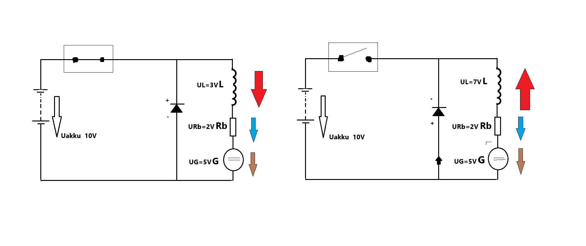
-The inductance of the motor generates a reverse voltage (U L) which is different at the moment of switching off and on.
-In the example, 3V at power on
-3V is an apparent loss which accumulates as magnetic energy
-internal resistance 2V
- generator voltage 5V
-In the disconnected state, the inductance of the motor generates a current in the opposite direction to the previous process, in the same direction as the battery current.
This current may be greater than the strength of the current flowing in (similar to the current of a parallel L-C resonance or even the solar MPPT charge controller) but not greater in energy content.
So this is basic D.C engine operation.
This is where the external energy added to the Adams engine comes from.
But from where?
This is where the combination of field energy and permanent magnet energy is inserted.
This whole study was done years ago, but now I have brought it up again.
I would like to point out that I did not do a full-scale authentic measurement! But since others have had similar results, the question is a given.
Either we have done the measurement wrong, or there really is something we have not noticed.
Basically I don't like battery arrangements because in my opinion they can deceive. In addition, it is not stable because of the charge-discharge ratios.
Now let's pick up the book again.
https://www.scribd.com/document/64950405/Egely-Gyorgy-Tertechnologia-3-kotet
This book was written years ago. One of the authors visited the workshop of Robert Adams. You can see it here starting at 2:20:26 (if you have any questions, feel free to ask, but I won't translate everything)
These machines, he says, are just to understand how it works. The real space-engineering extruder (I have to be honest, I don't like these terms, they may be correct, but I don't like them) has a different kind of operation. It is both conventional and etheric energy (remember that in Tesla's time, energy was called by several names).
"The unidirectional (pulsed) high voltage energy distorts the aether,which appears at a much higher speed on the surface of the coil,and thus delays or arrests the electron flow. This is why Ohm's law cannot be used. This creates a relaxation or rest period for the electrons. Mr Adams is confident that he can minimise the flow of electrons so that only the voltage is important."
Now let us savour this sentence.
What did Jagau say? What did Tesla say?
So a short one-way pulse.
That's what you find in the fighter ZPM generator (but it doesn't matter who invented what, just get to the point.That's why it's a pity that very few people have repeated the ZPM device)
So one important step is to collide the magnetic fields in the same direction. This is found in theEBM -C720 machine works similarly. From book 321. (COP -1.624)
I apologize for not writing the thoughts together. I'll continue.
Atti
This will be an excellent thread Atti.
We were able to see Dr. Robert Adams in his lifetime at the end of the video, I really appreciated it and moreover the translation was activated so easy to translate into our languages , thank you.
Jagau
What we consider to be empty space is merely a manifestation of unawakened matter. N.T.
Hi Atti
Question
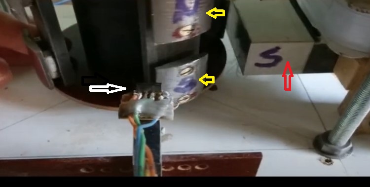
Did I identify the parts correctly?
White arrow = Hall sensor
Yellow arrows = are these two different magnets?
Red arrow = transformer core
It would be very interesting to see, if you have time, the shift in degrees between the pulse from the Hall sensor and that received at the gate of the Mosfet, when you have time. Nice work you have done here.
Jagau
What we consider to be empty space is merely a manifestation of unawakened matter. N.T.
Hi Jagau.
Yes, you have identified the parts absolutely correctly.
I took this type of engine apart years ago.
Only the rotor remains. So I can't take the measurement you asked for.
Generally speaking. The angular position defined by Robert is correct.
-The permanent magnet of the rotor is attached to the stator iron without any energy investment.
-Then you get a pulse.
-Then it only lasts until the surface of the permanent magnet touches the iron. So that's why the Hall transducer is a good solution.
Then, when loaded, the rotor speed increases. You can see this on the multimeter reading. That's what's important.
Atti.
Thank you Atti for explananation, like thoses drawings:
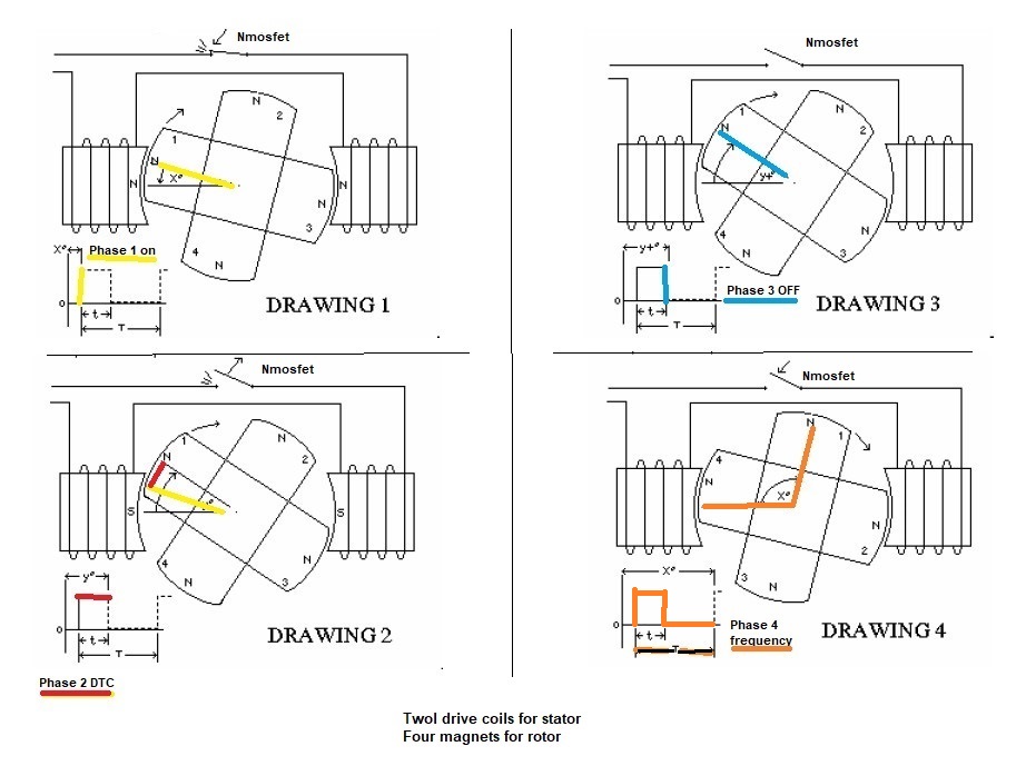
I divided them into 4 distinct phases exactly as the patent describes.
with some color notes added by me.
phase 1: The exact angle of the pulse must be in yellow. The on time is at yellow trace not before.
phase 2: Diagram 2: The pulse duty cycle in red
pahse 3: in blue the off time
phase 4: in orange time before the following pulse, including DTC and rest time. This is one cycle of the pulse. The frquency is the number of pulse in one second so it depend how magnet you have on the rotor.
the 4 phases are related to where the hall sensor is located, extremely important as you say, have I summarized correctly?
Immediately after the pulse occur several events occur.
1. the BEMF after the pulse reverses the polarization of coil over the iron and causes the next magnet to be attracted for free by the iron of the stator and the BEMF itself. The inversion time is exponential as Mr. Adams said.
2. The inertia of the rotor mass which is developed added to the bemf increases this force for free at each turn.
3. The more precisely the hall sensor is adjusted, the lower the consumption.
Jagau
What we consider to be empty space is merely a manifestation of unawakened matter. N.T.
Hi.
I think you summed it up quite well.
The reason you have to push the rotor by hand is because it can't start by itself because of the delay in the first phase. Here is a picture.
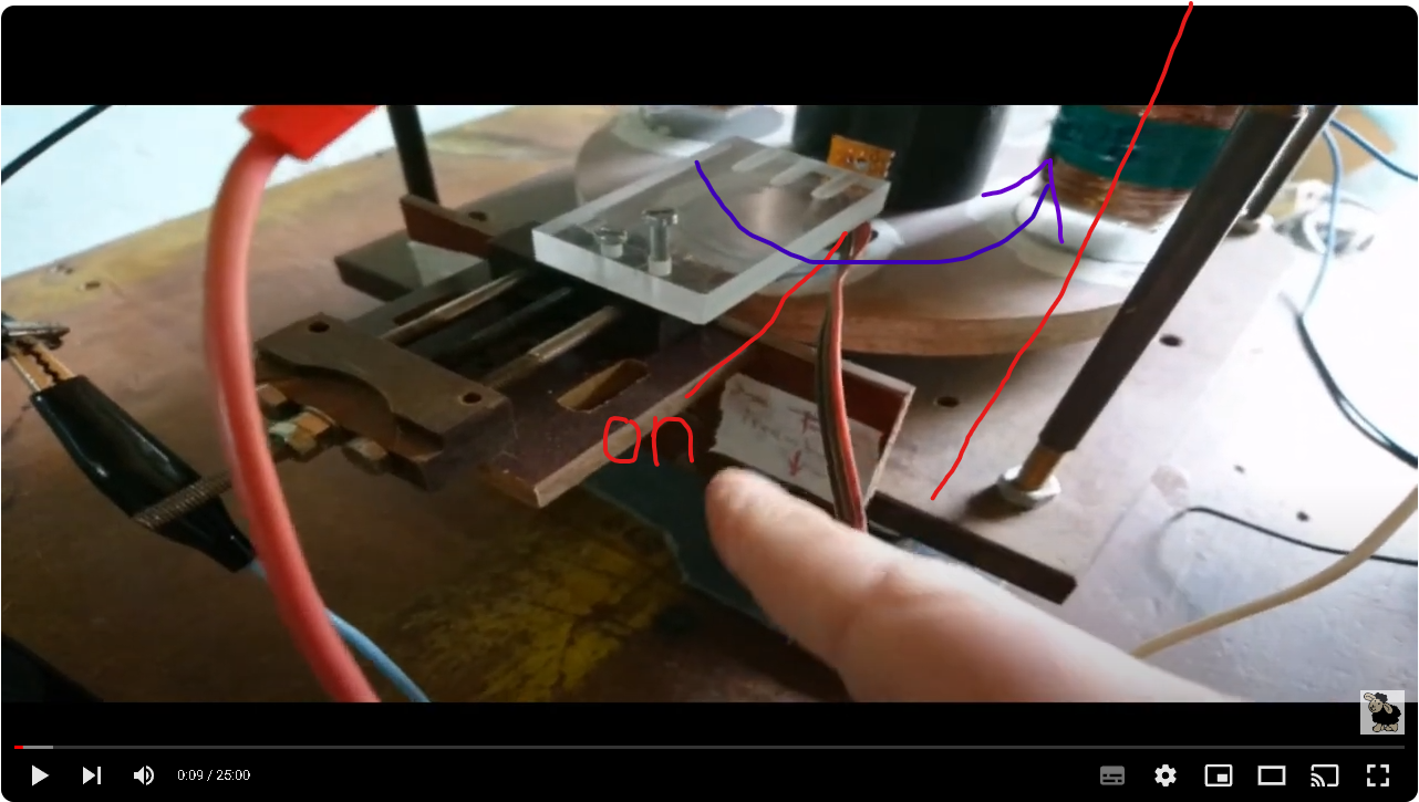
The rotor is already fully locked to the stationary part, and then only gets a signal after a small angle deviation.
I also made a star wheel for the linkage as recommended. Hall beacon is better to follow. Not only the switching angle but also the switching duration can be adjusted.
Think about it. In terms of switching time.
The center of the permanent magnet has a larger surface area,so that is the maximum switching time. The edge of a circular magnet has less surface area, so less switching time. I really like this method because you can adjust every time instant. Once you figure out the operation you can finalize the switching times by any method.
It's a very good way to charge the battery. I can't remember the exact efficiency , unfortunately I didn't write it in a note. And I will not say anything stupid (I repeat, I am not a battery person so I will not go into it further).
Atti.
In my opinion, there are even some similarities in other machines.
Note the identical repulsive poles. Also, in some machines the measurable excess energy is in the form of heat.
-Ebm C720 (with international measurement)
-Adams thermo motor
-oldmen motor (thermal energy measured at the switching element)
-not relevant but still worth noting. Fighter switch element extremely heated!
Accelerating angular position under load:
-Adams motor
-Bedini motor
-oldmen motor (closed poles)
(all tested)
Also interesting motors:
-Kohei Minato motor
-Harold Aspden motor
-The latter is similar to Teruo Kawai motor US5436518A
Atti.
Replying To: Atti
Excellent document, thank you very much Atti. With such detailed information from Mr.Adams it should be very possible to replicate.
Vidura