Clemente Figueras Generator

  • 3.5K Views
  • Last Post 14 November 2024
Vidura posted this 17 April 2024

Clemente Figueras Generator

Searching for the principles.

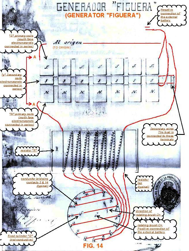
There was the Clemente Figueras thread on the AU forum many years ago, which I followed with great interest. Several talented builders were showing their skills and ideas. What was notable in my opinion, that all of them were convinced to know how it supposedly works and thus following more or less the same line. Eventually I have been scolded for proposing a different idea. The reason why different options should be explored is quite obvious: if it could not be replicated relaying on these ideas in 120 years, there could be a mistake in the interpretation of the patents. It is known that from the patent scripts several drawings had disappeared. It seems the only remaining is this block diagram:

The comments translated to English have of course been added by someone. Figueras himself never referred to the coil sets as “primary “ or “secondary” coils. He always described his machine as a generator and not as a transformer. What is the most important difference between them? On the internet we can find some answers, although doubtful ones. For example, that mechanical energy is converted into electricity in a generator, and that the changing magnetic field in the transformer induces a voltage in the secondary. The output voltage on the windings of the generator is not proportional to the number of turns ratio between the excitermagnets and the output winding. it is dependent on the magnetic field strenght, the rate of change per time unit and the number of turna on the outputwindings. I will come back to this later why I called doubtful such explanations. The most important difference is that the exciter magnet in the generator is continuously magnetized in the same polarity in contrast to the transformers primary. In this thread I will propose and test some different approaches to find the magic in this machine.

If we read the patents, it is quite straightforward explained how the machine resembles the operation of a standard generator or alternator without moving coils or other parts, with exception of the switching mechanism with brushes and a dc motor. But there is not one hint about how the reaction as per Lenz’ law is avoided. It is not too difficult to build a solid-state generator with a good efficiency. When I experimented with the DZ generator with rotating magnetic fields, I came to 95%+ but unfortunately not over 100%. This would be only possible by diminishing or cancelling the Lenz’ reaction. The numerous experiments I performed pointed to this direction.

So I will conclude this introduction with the statement: if we don’t understand how it works we cant likely reproduce it. And even if someone succeeds by trial and error without understanding how, it is not likely replicable for others. This applies for other inventions and devices as well.

will continue soon 

Vidura

Jagau posted this 29 April 2024

Hi Vidura, nice experiment

I don't know the Figueras patent well, but if I remember correctly in my archives I had a document that I reread and he too, like many others, the basis of his patent is that he collects Electrostatic charges of the atmosphere.
Did you read somewhere if he meant the presence of aether??

Because to me it seems the same.
Reads the attached PDF document from my archives on Figueras.

Jagau

Attached Files

Vidura posted this 29 April 2024

Replying To: Jagau

Thanks’ for the document, the drawing of the first device is of interest, I saw this time ago on the real strannik forum. It also suggests closed magnetic paths with a gap. Having read the patents in Spanish languish I must say that nowhere is mentioned that the induced has no core, the only thing that was stated by Buforn in a later patent script, that it was not necessary to leaf spaces between the exciter magnets and the induced, as there was no mechanical movement. There was also some information, I don’t know the exact source, that Figueras ordered the core material in Germany from a renamed factory, and out of curiosity they offered to send an assistant to canary island to "help to assemble the device" which has been declined by Figueras. If this information is authentic it is not likely that soft iron was used for the cores.
Regarding the atmospheric electricity, in the patents there is no hint for that, only several times the device is compared with the dynamo machine, and the interaction of magnetic fields. It might be comments from contemporary newspapers, as the expression electrogen or electric fluid was used at this time.
For the moment I will continue to collect empirical data from experiments and try to find out how it works.

Vidura

Vidura posted this 07 May 2024

Here an update. Some more tests have shown that the response of the electromagnets is way to slow. To build up the rated current of 1 A approximately, I would have to lower the frequency to a few Herz, which of course will not produce a significant induction neither. A test with 164 ohm resistors in each channel showed that both, rise- and fall-time of the current is still too slow. To improve the rise-time the voltage could be increased, and for the fall-time the resistance has to be still larger. The resistors should not dissipate significant energy from the source, but only decrease the current of the electromagnets at a fast rate when the switches change (then the BEMF will rise the voltage to a much higher level). For this I will need some power resistors of higher values (difficult for the moment due to the economic situation). Another option would be to rewind the electromagnets with less turns and a higher current capability, so decreasing the inductance would also improve their time response.

So far for the actual setup, it is crucial to make the electromagnets change at a fast rate to get significant induction.

On the other hand, I found important information in the 1902 patent scripts, thanks to Jagau for the hint. In an internet archive I found four patents of that year, I will attach the files below. The first three describing a generator which has electromagnets in the outer stator, and others in a second central stator with a space in between, where the coreless(!) rotor with the output coils is spinning. The Autor states that this way the Lenz force become insignificant and only a very small force is required to spin the rotor.

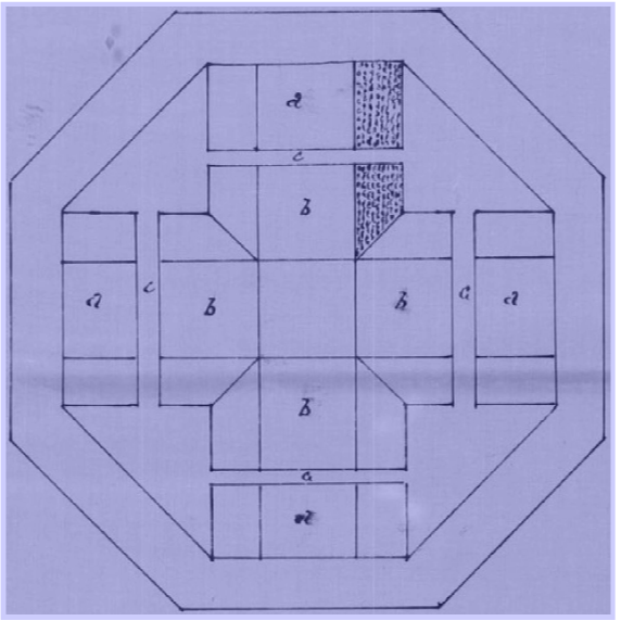
In the last patent the rotor is no more required, as the variation of the magnetic fields is produced by varying the current of the exciter magnets. This last one would correspond to the drawing below:

For the first three patents a rounded shape with a slightly wider space between the magnet faces would be used. For the last one this shape could be a good approximation. An important detail: in all descriptions it is very clearly specified that the electromagnets are set in ATRACTION MODE, with unlike poles facing each other. 

It is also stated that in the gap between them, which should be made as small as possible, the induced(output coils) is placed. This suggests that the induced don’t have a core for their own.

Will continue soon…

Vidura

Attached Files

Vidura posted this 08 May 2024

Some more testing performed: 

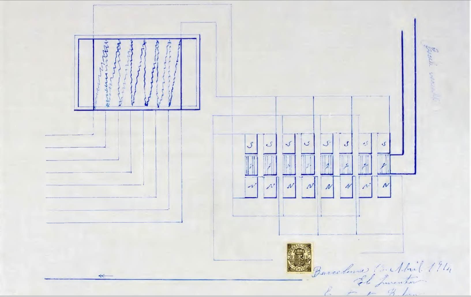
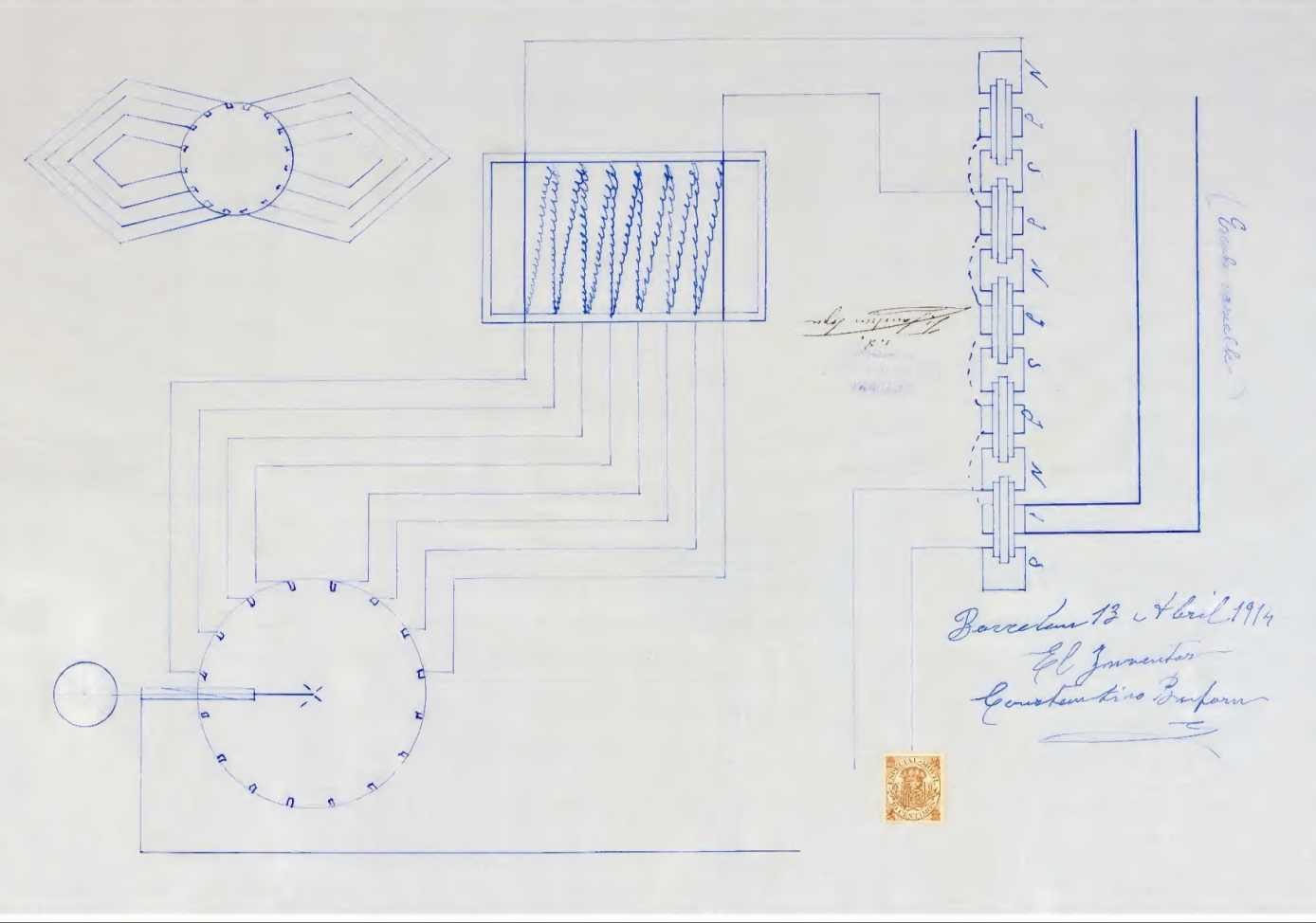
These tests make it clear that the inductance of the exciter coils has to be smaller. For this reason, in the patent drawings, they are shown connected in parallel while the output windings are series connected. As I believe that the clue for this device can be found in the 1902 patent scripts, I will change the setup to try the concept of coreless output windings placed in the gap between two strong varying magnets in attraction mode.

In the drawing of the 1914 patent filed by Constantin Buforn, which has been verified for practical operation by an agent of the Spanish patent office, the connecting scheme can be viewed. Also there are some components between the coils in the drawing, which likely could be nonmagnetic spacers according to the latest interpretation.


Vidura

Vidura posted this 11 May 2024

Here some explanations about the findings in the patent scripts and planned experiment:


Vidura

Vidura posted this 11 May 2024

Hello All!

To open posibillities to join this research and experiments for new members also, i changed it to a category with general access.

Regards.

Vidura

Vidura posted this 15 May 2024

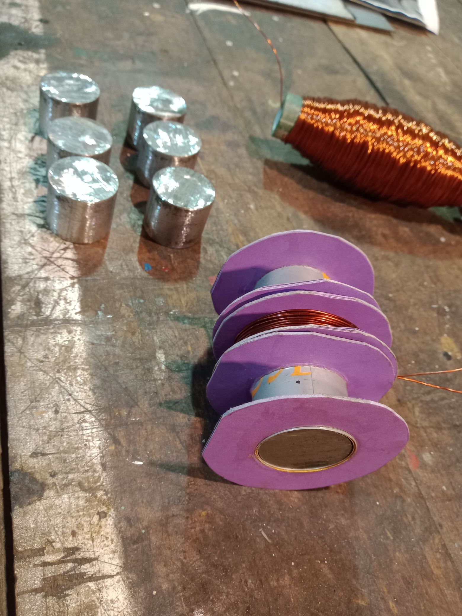
Despite of a very busy and challenging time I could advance a bit with the new experimental setup. The coil formers are made from cardboard and carpenter glue and I got some pieces of low carbon steel (Aisi 1010 grade) for the cores. Also, one of the big electromagnets from the former setup has been unwound to recover the copper wire. The induced(output) coil is wound over a small piece of wood dowel as spacer, to support the attractive force of the electromagnets. 

Vidura

Vidura posted this 16 May 2024

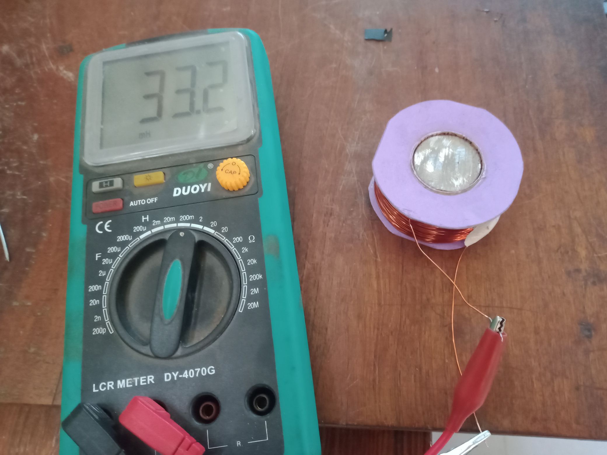
Today I finished one electromagnet coil. The test showed that the 1010 grade steel is not suitable as core material, the field was weak. Here the value:


When I repeated with another steel core (unknown composition) it was better, but the best result gave a bundle of iron nails, where the inductance doubled and also the attractive force with the same current. Ideally, I would prefer silicone steel or even better permalloy, but for the moment I have to use materials from scratch. Also, the inductance should be higher, estimated 100 to 200mH for a frequency around 50hz, so I will wind a pair of magnet coils with more turns.

Vidura

Vidura posted this 21 May 2024

Here a short video with some results and next steps for the research.

Vidura

Vidura posted this 23 May 2024

Hi All!

Today I performed a test about the idea with the new core and coils configuration. It looks promising.  Here a video with the demonstration:

Despite of the precarity of the setup it demonstrates that it is working as generator in this configuration, and not as transformer. There are some interesting details to discuss. It is evident by the winding’s ratio between exciter coils and induced coil that the induction occurs in generator mode. But on the output trace it is clearly visible that not the shape of the current trace, but the voltage steps are reflected. A challenge to explain with Faradays law of induction. Another very interesting observation I could make is that by shorting the terminals of the induced coil the current measured on the exciter coil increased, but the current drawn from the power supply remained constant.

Vidura

Close