Clemente Figueras Generator

  • 2.9K Views
  • Last Post 1 weeks ago
Vidura posted this 17 April 2024

Clemente Figueras Generator

Searching for the principles.

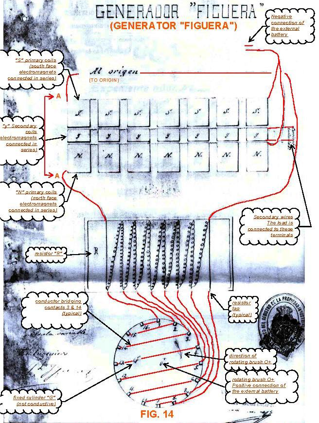
There was the Clemente Figueras thread on the AU forum many years ago, which I followed with great interest. Several talented builders were showing their skills and ideas. What was notable in my opinion, that all of them were convinced to know how it supposedly works and thus following more or less the same line. Eventually I have been scolded for proposing a different idea. The reason why different options should be explored is quite obvious: if it could not be replicated relaying on these ideas in 120 years, there could be a mistake in the interpretation of the patents. It is known that from the patent scripts several drawings had disappeared. It seems the only remaining is this block diagram:

The comments translated to English have of course been added by someone. Figueras himself never referred to the coil sets as “primary “ or “secondary” coils. He always described his machine as a generator and not as a transformer. What is the most important difference between them? On the internet we can find some answers, although doubtful ones. For example, that mechanical energy is converted into electricity in a generator, and that the changing magnetic field in the transformer induces a voltage in the secondary. The output voltage on the windings of the generator is not proportional to the number of turns ratio between the excitermagnets and the output winding. it is dependent on the magnetic field strenght, the rate of change per time unit and the number of turna on the outputwindings. I will come back to this later why I called doubtful such explanations. The most important difference is that the exciter magnet in the generator is continuously magnetized in the same polarity in contrast to the transformers primary. In this thread I will propose and test some different approaches to find the magic in this machine.

If we read the patents, it is quite straightforward explained how the machine resembles the operation of a standard generator or alternator without moving coils or other parts, with exception of the switching mechanism with brushes and a dc motor. But there is not one hint about how the reaction as per Lenz’ law is avoided. It is not too difficult to build a solid-state generator with a good efficiency. When I experimented with the DZ generator with rotating magnetic fields, I came to 95%+ but unfortunately not over 100%. This would be only possible by diminishing or cancelling the Lenz’ reaction. The numerous experiments I performed pointed to this direction.

So I will conclude this introduction with the statement: if we don’t understand how it works we cant likely reproduce it. And even if someone succeeds by trial and error without understanding how, it is not likely replicable for others. This applies for other inventions and devices as well.

will continue soon 

Vidura

Jagau posted this 17 August 2024

Hi Vidura
Research is not easy, I know something about it, we must constantly encourage ourselves and start again.

While browsing the web I noticed a researcher who makes a good analysis of the subject in which your research goes. To give you new ideas or maybe another point of view I indicate a link on Clemente Figuera that will interest you, maybe?

Clemente Figuera: A layman assimilation through analysis and discovery

by Jose Antonio

https://open-source-energy.org/?topic=3666.msg59007#msg59007

Good reading

And a small pdf on the subject
Jagau

Attached Files

AbitAnnoying posted this 17 August 2024

Hello. Isn't the purpose of this device just to make the DC voltage of the battery more or less a sine wave so that it can then be increased or decreased with a transformer? It seems like a very old invention, at that time there were no DC/AC converters and probably not even well available active elements, so he did it using resistors and a motor... Such a primitive "inverter"??

Vidura posted this 17 August 2024

Quoting:AbitAnnoying

Hello. Isn't the purpose of this device just to make the DC voltage of the battery more or less a sine wave so that it can then be increased or decreased with a transformer? It seems like a very old invention, at that time there were no DC/AC converters and probably not even well available active elements, so he did it using resistors and a motor... Such a primitive "inverter"??

You are correct with this, it was just the way switching was done at those times usually, and if the device is built properly the losses of the resistor network could be neglected. The challange is to find the engeneering solution to get the timeresponse of the coils and the impedance mached to the resistor network and operating frequency. And more than anything else how to deal with the counter EMF of the generated outputcurrent and use it to assist the magnetic primary fields.

Vidura

xman posted this 18 September 2024

I found an interesting video.maybe the longer the core, the smaller the BEMF. Maybe your core length in the middle is too short. Clemente Figuera never said how long the core was, he just drew a diagram. It's just my two cents.😄

Vidura posted this 19 September 2024

Replying To: xman

Hi xman. Regarding the lenght of the core I would agree, it might have been to short in the last setup. 

But what mr. Elliot is showing is a different thing, if you pay attention the poles of the attached neomagnets ar like towards the steelrod. So it is a common effect of leaking out flux of that polarity over the whole rod which under this condition can not polarize but only conduct the flux of the neomagnets. In the case of Figueras second patent , if we can trust the information we have, the centrecore is polarized all the time, only with alternating intensity on both ends, which would move the blochwallover the winding inducing an EMF on the output. I have shown this configuration in an earlier experiment, the concept is valid, but still the correct geometrie and materials have not been found.

Regarding the counter magnetic force as per Lenz' law My hypothesis is different, but I will not go into that until finding consistent proofes.

Thanks for the feedback 

Vidura

Vidura posted this 23 September 2024

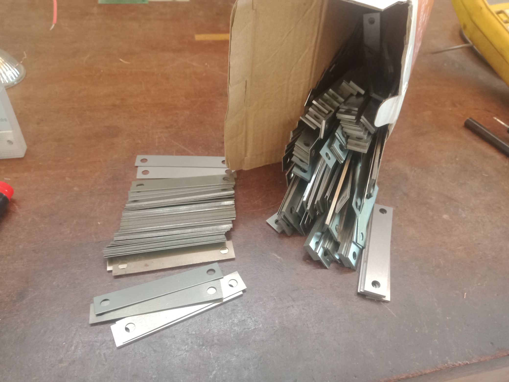
Short update: I have received today a batch of I laminations to test some more geometric arrangements. Got them for an affordable price, less than 2$ per kg. This will save a lot of time , as the recycling of these materials is very timeconsuming.

So this Project has not been burried, will continue.

Vidura

Vidura posted this 14 October 2024

Back on this topic, as I have stated before in the next experimental setup an almost closed magnetic circuit will be used. A feeling is telling me that the first configuration could be close to the truth:

In this setup the greatest problem was that the coils had a far to large inductance and thus the rise and fall time of the current was too slow. Another drawback was the difficulty to vary the gaps, I think there was also flux leaking from one side to the other, instead of going across the output core.


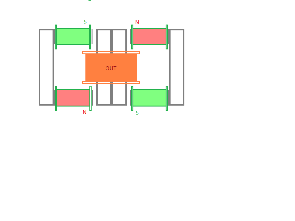
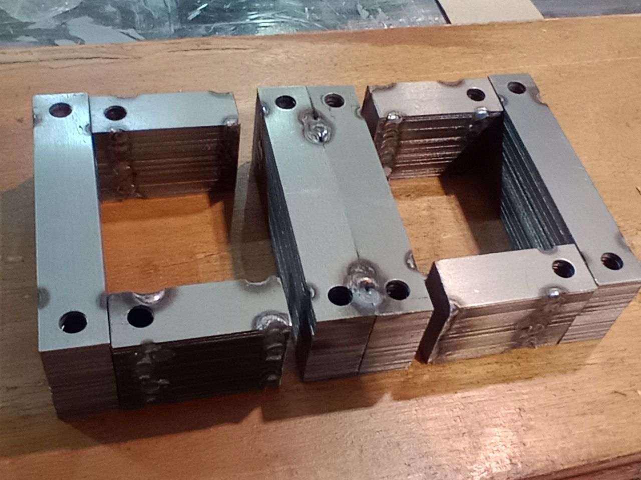
For the new setup I will use I-laminations from transformer silicone steel. It is superior to the motor cores, which are mostly made of low carbon steel sheets. The geometric form will look like this:

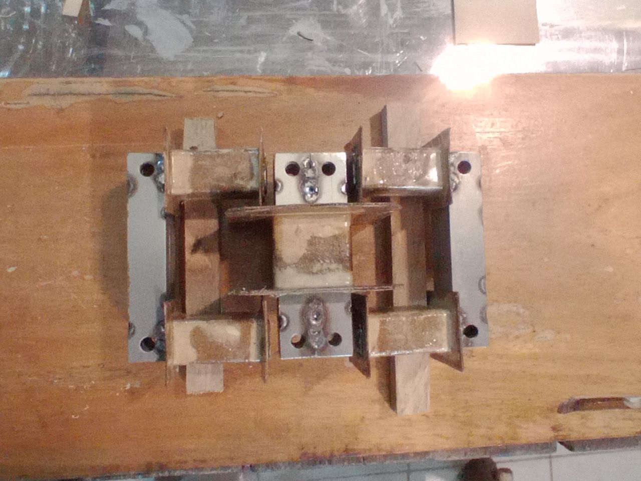
With this shape it will be easy to modify the gap size and also to change the winding parameters if necessary.                                               The electromagnets will be alternately varying in intensity, when the left pair is at maximum current, the right pair will be at minimum. Note that much like in the conventional generator the maximum of the output current occurs when both sides are active with equal strength, or when the rotor position is perpendicular to the axis of the output coil.   I found some interesting information on this YT video. It is explained that in magnetism there are two actions present, first the magnetization which is a torque acting on the magnetic domains, and it diminishes with the inverse square of the distance. The other action is the force of magnetic attraction on the already aligned domains, and it diminishes with the inverse cube of the distance. He gave mathematical foundations of that, for those with more skills in math’s it might be interesting to dive deeper into the work presented on the channel. But from these statements we can draw important conclusions. As I am curious, I made some of the simple experiments playing with magnets and coils, and it can indeed be observed, that the force of magnetization reaches out farer than the force of attraction. For this reason, I am working on the new setup with variable gap size.

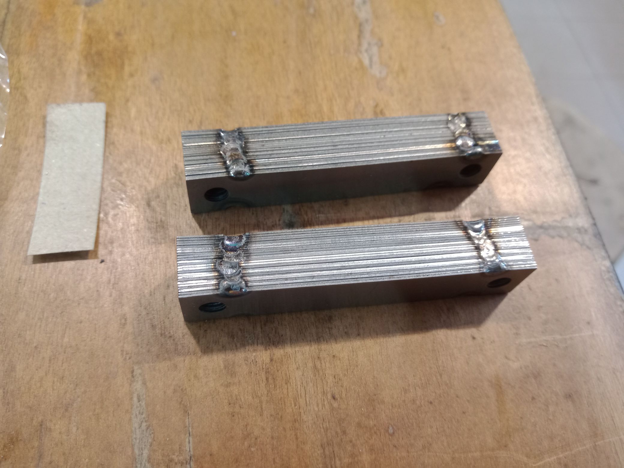
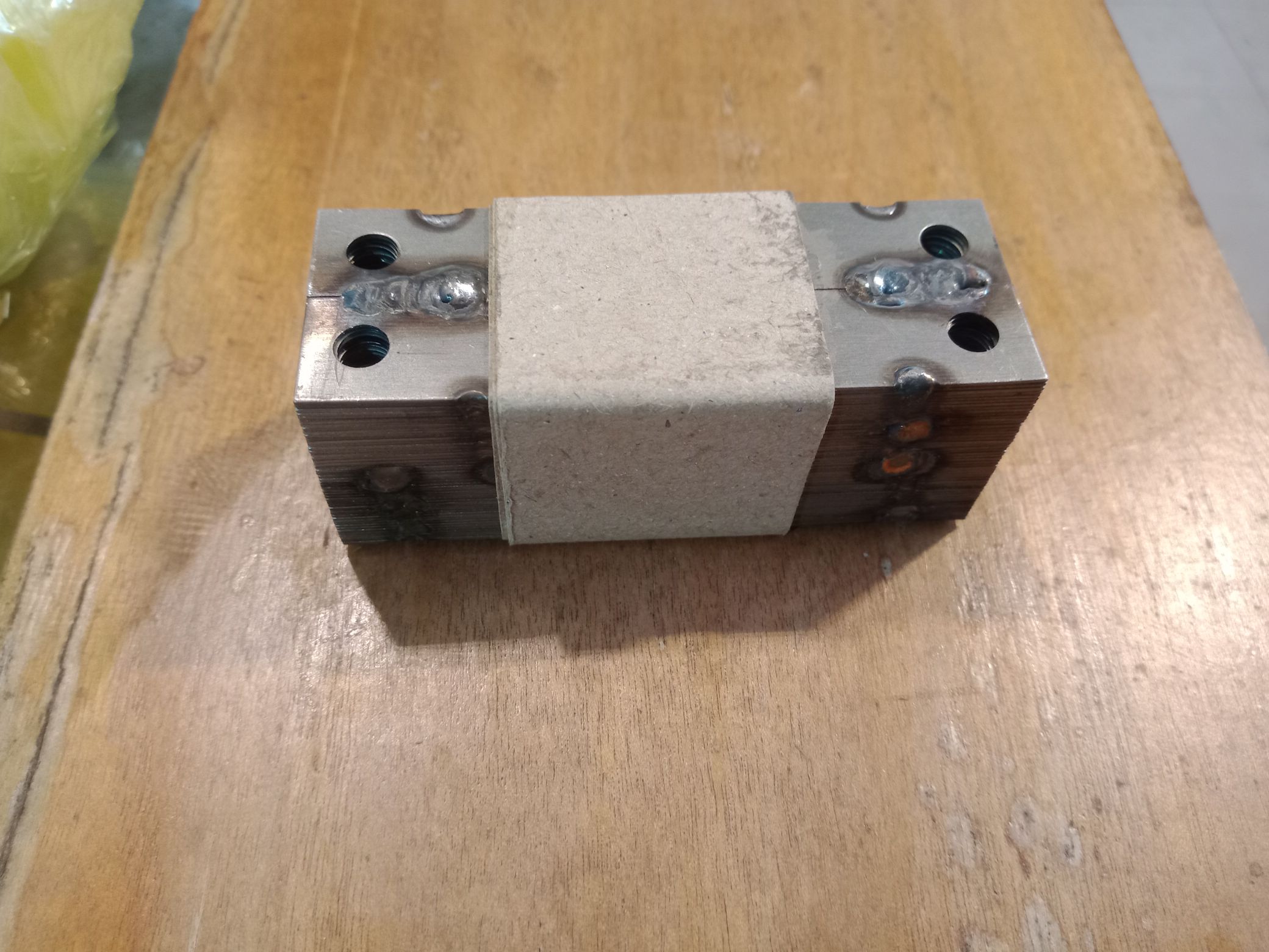
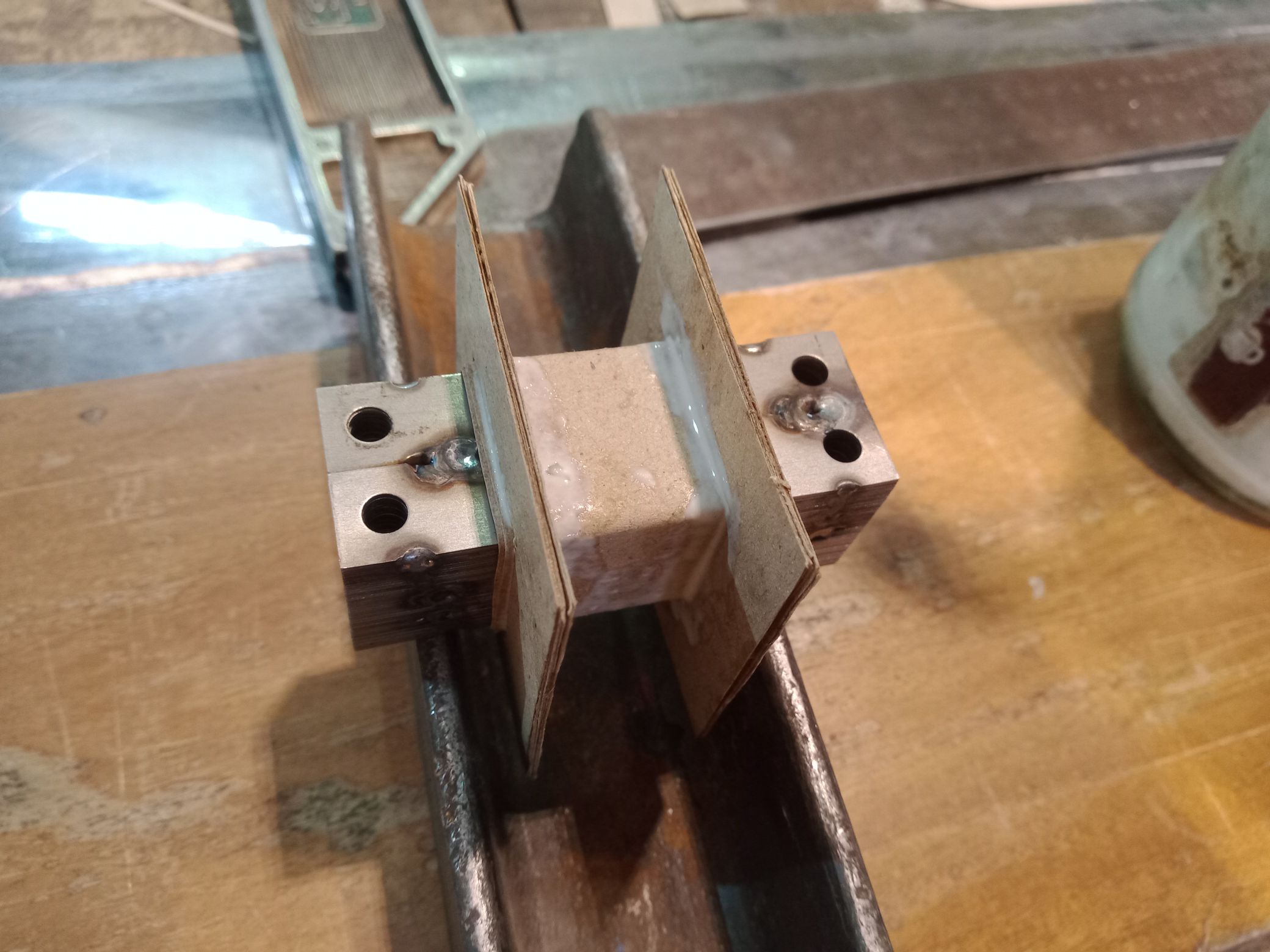
As it was not coming out well to join the laminates with resin, they have an insulating coating very difficult to remove which don’t adhere, so I fixed the assemblies with TIG welding. Below some images from the progress:

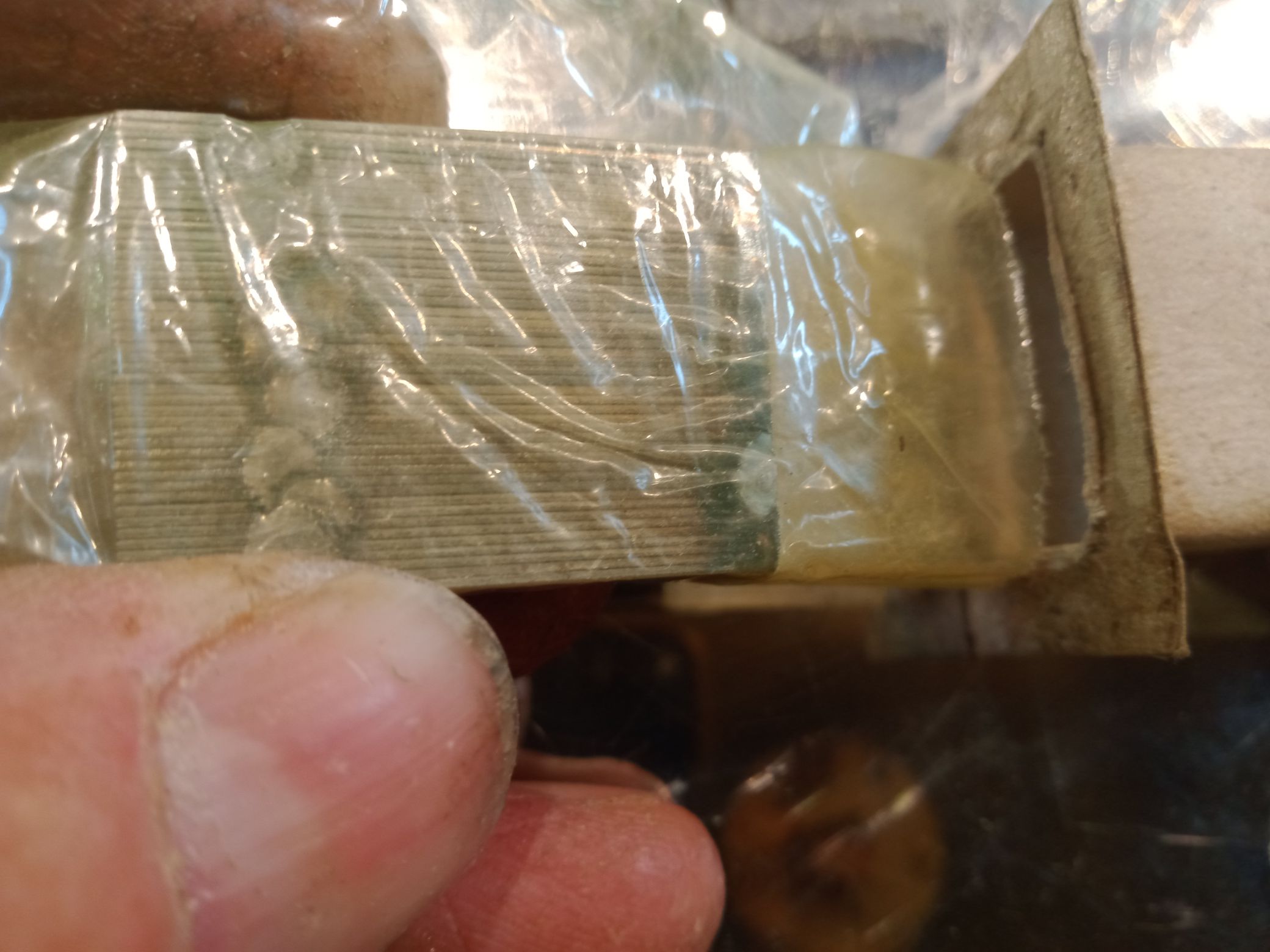
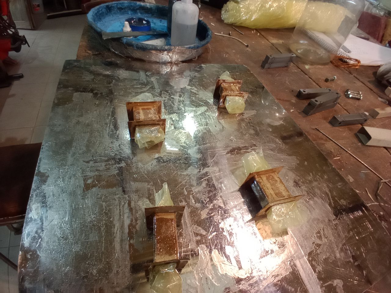
The coil formers are made of cardboard glued and after resin coated.


Vidura

Jose Antonio posted this 17 October 2024

Really nice Build Skills! 

Question regarding the picture in your first post. Do you know the history or where it came from?

The words Al Origen can be interpreted in many ways. The direct English interpretation is exactly as written (To Origin), but it would be used more as a phrase that would translate "Where it Begins" or "To the Beginning".  Kinda like when Star Wars uses the phrase "In a Galaxy Far Far Away,"  they are referring to the Origin being a distant galaxy.

I think this is important because the Negative terminal would not be considered a beginning or a point of beginning. Curious if this was added by a user or part of the original patent documents. If original, I would be very excited to hear that. 

Keep up the GREAT work!

-JA

Vidura posted this 19 October 2024

Question regarding the picture in your first post. Do you know the history or where it came from?

The words Al Origen can be interpreted in many ways. The direct English interpretation is exactly as written (To Origin), but it would be used more as a phrase that would translate "Where it Begins" or "To the Beginning".


Hi Jose, I would translate "al origen" in the context of a drawing  as "to the beginning" which seems to make reference to the beginning of the resistor array. Unfortunatly I have no exact information of the source, i get all the information from the internet and the patent documentation


Vidura

  • Liked by
  • Fighter
  • Inception
Vidura posted this 19 October 2024

In the video below there are the simple magnet and coil experiments which led me to the actual configuration:

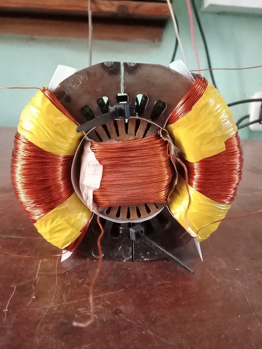
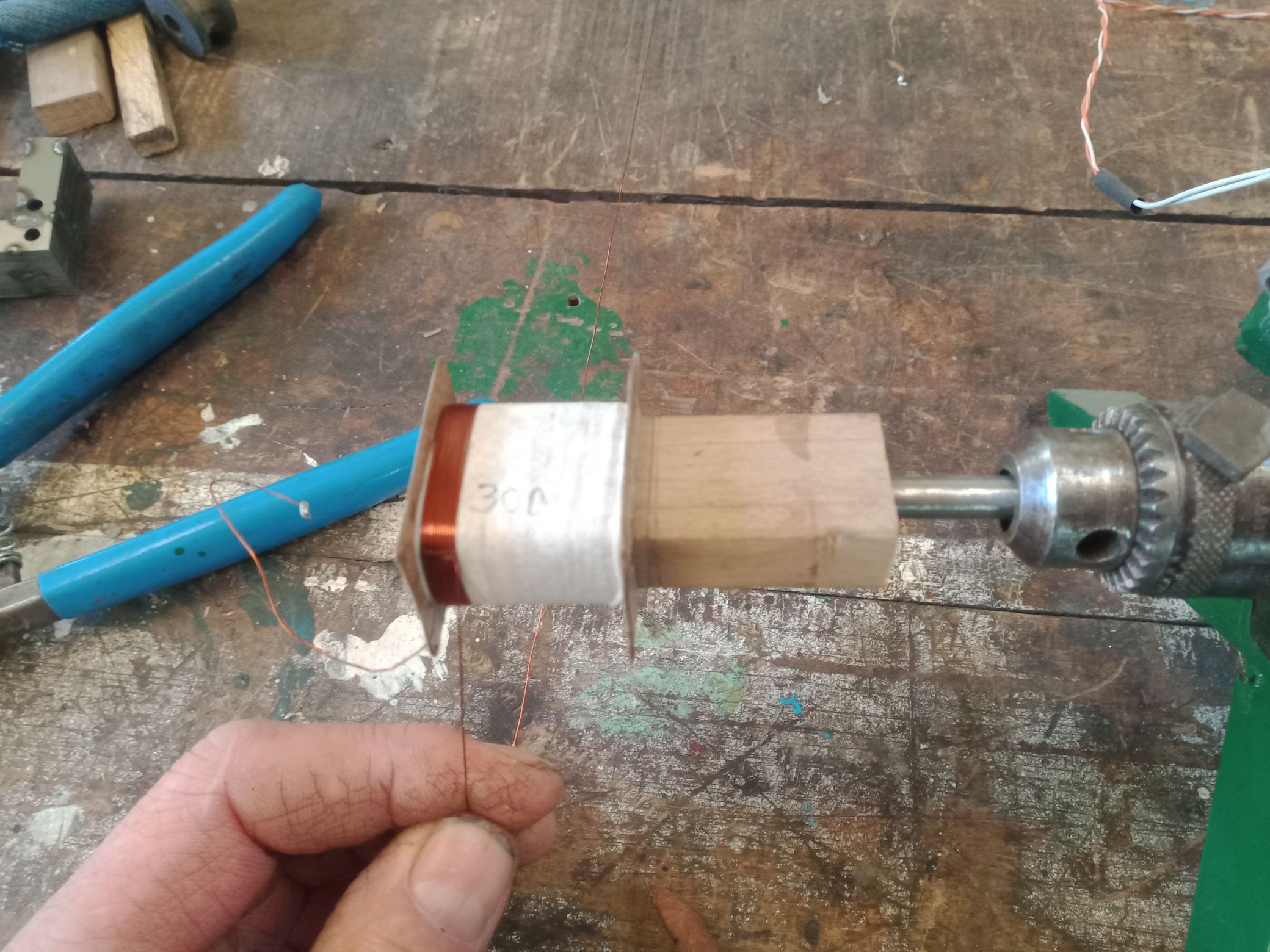
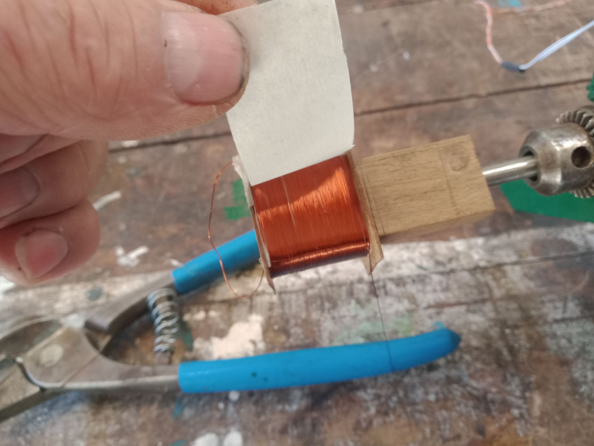
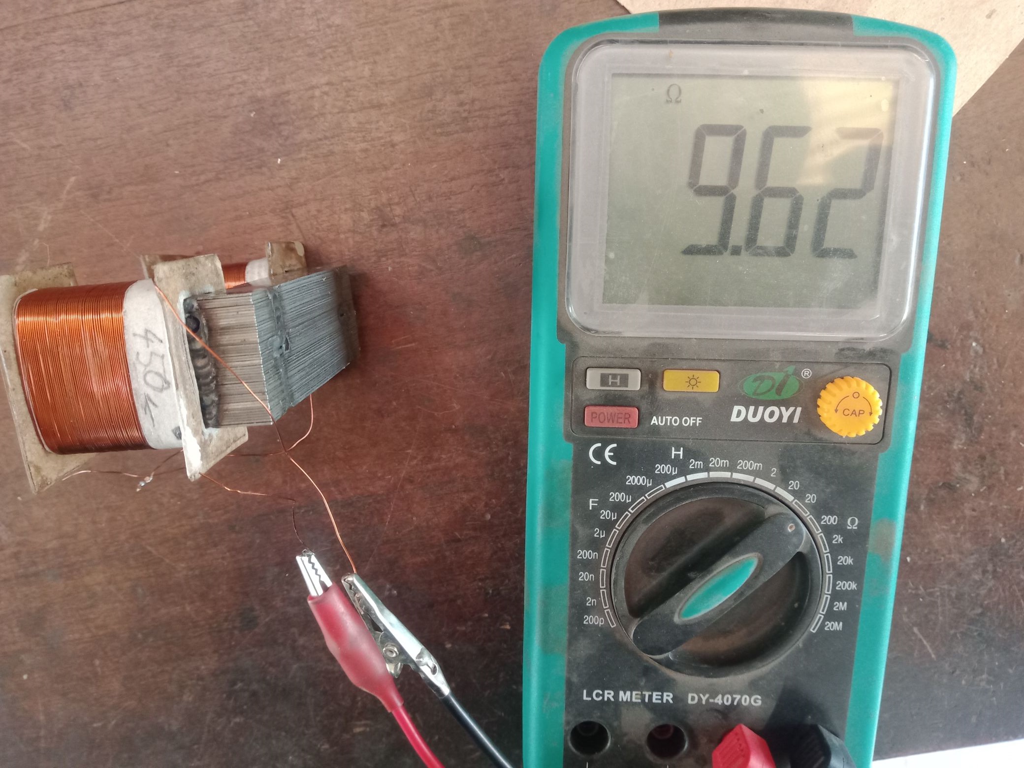
 Here I will continue the documentation of the practical implementation, hopefully it inspires someone who wishes to make a replication or similar experiment to realize his project. Below the winding of the first Electromagnet. The coils have 450 turns each of 0.3mm magnetic wire and each layer is separated from the previous with masking paper tape:


I did not take the picture of the inductance measurement, it is 20mH each coil with open core.

Here the test of the electromagnet.

Vidura

Close