Clemente Figueras Generator
Searching for the principles.
There was the Clemente Figueras thread on the AU forum many years ago, which I followed with great interest. Several talented builders were showing their skills and ideas. What was notable in my opinion, that all of them were convinced to know how it supposedly works and thus following more or less the same line. Eventually I have been scolded for proposing a different idea. The reason why different options should be explored is quite obvious: if it could not be replicated relaying on these ideas in 120 years, there could be a mistake in the interpretation of the patents. It is known that from the patent scripts several drawings had disappeared. It seems the only remaining is this block diagram:
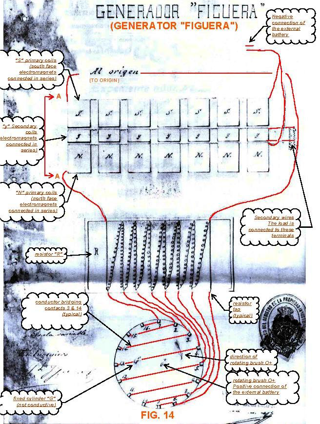
The comments translated to English have of course been added by someone. Figueras himself never referred to the coil sets as “primary “ or “secondary” coils. He always described his machine as a generator and not as a transformer. What is the most important difference between them? On the internet we can find some answers, although doubtful ones. For example, that mechanical energy is converted into electricity in a generator, and that the changing magnetic field in the transformer induces a voltage in the secondary. The output voltage on the windings of the generator is not proportional to the number of turns ratio between the excitermagnets and the output winding. it is dependent on the magnetic field strenght, the rate of change per time unit and the number of turna on the outputwindings. I will come back to this later why I called doubtful such explanations. The most important difference is that the exciter magnet in the generator is continuously magnetized in the same polarity in contrast to the transformers primary. In this thread I will propose and test some different approaches to find the magic in this machine.
If we read the patents, it is quite straightforward explained how the machine resembles the operation of a standard generator or alternator without moving coils or other parts, with exception of the switching mechanism with brushes and a dc motor. But there is not one hint about how the reaction as per Lenz’ law is avoided. It is not too difficult to build a solid-state generator with a good efficiency. When I experimented with the DZ generator with rotating magnetic fields, I came to 95%+ but unfortunately not over 100%. This would be only possible by diminishing or cancelling the Lenz’ reaction. The numerous experiments I performed pointed to this direction.
So I will conclude this introduction with the statement: if we don’t understand how it works we cant likely reproduce it. And even if someone succeeds by trial and error without understanding how, it is not likely replicable for others. This applies for other inventions and devices as well.
will continue soon
Vidura