Fighter's ZPM (Zero Point Module) failed replication by Itsu

  • 8.6K Views
  • Last Post 18 December 2022
Itsu posted this 07 November 2022

Hello all,

i opened this thread to discuss my replication of Fighter's ZPE (Zero Point Module).

I already opened a similar thread on OUR.com (https://www.overunityresearch.com/index.php?topic=4374.msg101654#msg101654 ), but will transfer some data from there to here.

Initially i understood that the below diagram was correct and complete, but it turns out its not.
There is a ground connection somewhere, but i am not sure where it is exactly, hopefully someone can tell me.
The MOSFET is shown wrong as the Drain and Source should be swapped, which was corrected later in Fighter his thread so therefor the mentioning in red.

I have build up a similar circuit and the data is shown here: 
(Be aware that the induction measurement was done at 10kHz, but due to the influence of the metglas core it can be (and is) completly different on other frequencies, see my thread on OUR.com for a VNA scan of the coil/core)


I am using a 12V battery for now as my PS (minus NOT grounded) was acting weird due to all the pulses coming back from the ZPE device.
Up till now no special effects or resonance in a 0 to 5MHz range are seen with this setup, but as said the grounding may be the problem here.

Itsu

Order By: Standard | Newest | Votes
Itsu posted this 07 November 2022

Hello all,

i opened this thread to discuss my replication of Fighter's ZPE (Zero Point Module).

I already opened a similar thread on OUR.com (https://www.overunityresearch.com/index.php?topic=4374.msg101654#msg101654 ), but will transfer some data from there to here.

Initially i understood that the below diagram was correct and complete, but it turns out its not.
There is a ground connection somewhere, but i am not sure where it is exactly, hopefully someone can tell me.
The MOSFET is shown wrong as the Drain and Source should be swapped, which was corrected later in Fighter his thread so therefor the mentioning in red.

I have build up a similar circuit and the data is shown here: 
(Be aware that the induction measurement was done at 10kHz, but due to the influence of the metglas core it can be (and is) completly different on other frequencies, see my thread on OUR.com for a VNA scan of the coil/core)


I am using a 12V battery for now as my PS (minus NOT grounded) was acting weird due to all the pulses coming back from the ZPE device.
Up till now no special effects or resonance in a 0 to 5MHz range are seen with this setup, but as said the grounding may be the problem here.

Itsu

Itsu posted this 07 November 2022

I understand from Fighter that his PS minus lead is connected to chassis ground and thus earth ground.

My severall PS's all have NO connection from their minus leads to chassis ground / earth ground.

Are there more members having a PS which has its minus lead connected to chassis / earth ground?

Thanks Itsu

editor posted this 07 November 2022

Hi Itsu, 


My PS has minus terminal and ground chassis / eart ground connected.


brd

YoElMiCrO posted this 07 November 2022

Hello everyone.

Welcome Itsu.
Almost all power supplies have the negative to ground.
I think the best idea is to power it with batteries, as you do.
That way the system is really isolated, on the other hand
measure the current with a transformer and visualize on the oscilloscope.
Fighter ZPM modulates core magnetic permeability in contrast 
it is normal for the LENZ law to appear.
I have dedicated a lot of study to ZPM, for several phenomena that I have seen
in it, but I still do not finish studying it.

From now on thank you.

YoElMiCrO.


Itsu posted this 07 November 2022


Thanks editor and YoElMiCrO,

good to know, i must then have 3 different lab PS's which have their minus / negative lead NOT connected to ground.

So i can place the ground point in the above diagram on the PS minus / negative connection.

I understand from the Fighter thread that there must be a ground connection for the "effect" to show up, so i will ground my battery minus lead and retest.

Itsu

Itsu posted this 07 November 2022

A new sweep from 0 to 5MHz now with the earth ground connected to the minus lead of the battery does not show any resonance or decrease of current effect.

Using a similar PS (Manson SPS9400) as shown by Chris in his thread (0-15V @ 40A) which has its minus lead NOT connected to ground does show some resonance around 62kHz but only when connecting an earth ground to the minus lead which confirms the need for a grounded minus lead.

But no decrease of the input current is noted during this resonanse and the bulbs (2x 12V / 21W) stay on normally.

Itsu 


Itsu posted this 08 November 2022


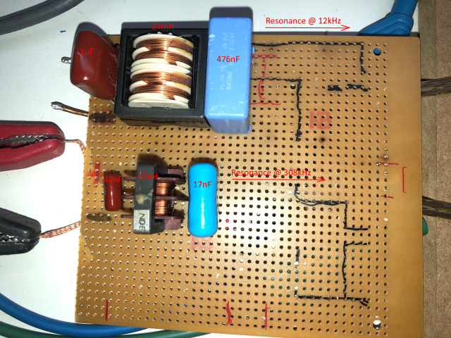
As can be seen in my thread on OverUnityResearch.com, i build a low pass filter to protect my PS from failing due to the spikes the ZPM produces during operation.
It caused my PS to make all kind of strange noises and had the current limiter activated randomly etc. so i was forced to use a 12V battery for initial testing.

This 1st low pass filter worked fine and present to the PS an almost straigth DC and no more problems.

But as a side effect, it seems to cause the ZPM to get into resonance around 12kHz which i first tought it was the resonance from the ZPM itself.
It turns out after testing this low pass filter with my 12V battery that it is the cause of the resonance as without the filter i have NO resonance in the ZPM in a 0 to 5MHz range.

So i build another low pass filter using different components and indeed this one also gets the ZPM into resonance (on battery) but now around 308kHz.

The purpose of this post is to make you aware that a filter in a power source has influence on the ZPM in that it is "a" cause of the resonance of the ZPM.
Exactly like Fighter shows, at this resonance frequency, the input current reduces to almost 0mA, but as a big difference with Fighter, my ZPM lamps go out then 😒

Picture of both low pass filters:


Itsu

Itsu posted this 08 November 2022


After reading the by me accessible threads and my own experiments, i think i can name the below facts.
Please correct me if wrong, but please present some data to show what is wrong.

# Fighter shows us his effect as being 2 or more 12V bulbs nearly fully lit when the ZPM is at resonance causing the DC source input current meter decreases to near 0mA.
See this post video around the 3:50 min mark:  https://www.aboveunity.com/thread/romanian-zpm-zero-point-module/?order=all#comment-4b4524d9-81b1-4605-b930-aa71010a436b

# No one replicating this ZPM was able to show the same effect meaning: 2 or more 12V bulbs nearly fully lit when the ZPM is at resonance causing the DC source input current meter decreases to near 0mA.

# No one replicating this ZPM besides me has the coils in the same spot as Fighter meaning at the short part of the cores (not sure this is crucial).

# Replicators using a battery as input do not report seeing any resonance in their ZPM.

# low pass input filters in a DC source can cause a resonance as seen in the ZPM.

# a ground connection on the negative lead of the DC source is needed to have resonance in the ZPM together with any filtering in the DC source.

  
Please comment,   regards Itsu
 

Vidura posted this 08 November 2022

Replying To: Itsu

Hi itsu, welcome on the forum. To be clear, I have only spent a couple of hours trying to replicate the ZPM, but Yoelmicro and me did a lot of experiments with parametric resonance coils, which I think could be part of the observed effects.As Fighter stated, the PS seems to be part of the resonant circuit. If you use a filter like shown in the image above, this will certainly change the Resonant frequency, mostly the capacitor on the side of the ZPM. You could try a RCL filter with a cut off frequency ~ 40khz to isolate the PS, the resistor on the output would dampen the oscillations better. Regarding the resonance I am convinced that it is wave resonance, ant therefore other parameters has to be taken in account also. For example the distributed capacitance of the coils, the capacitance with the core(which layers are closer to it, where connected to the centre tap) and also the length of wires , inductance including the connections to external components. Fighter has reported the influence of the connections to the lamps, which indicates the presence of a standing wave in the circuit. Hopefully this gives some ideas to progress.

Vidura

Atti posted this 08 November 2022

Welcome Itsu!


# No one replicating this ZPM besides me has the coils in the same spot as Fighter meaning at the short part of the cores (not sure this is crucial).

I apologize for not replying as the addressee. I won't answer for him. Fighter will then make his own opinion on your question.

(Perhaps I am the only member who does not speak English and I use google translator. In several cases, members have indicated that sometimes what is being said is incomprehensible. If this bothers you, please ignore this)


I can't speak for anyone else, but I did some experiments. But only in my own way. (as far as I know, others have also completed these courses) So not with the exact materials, but according to my possibilities. I couldn't work with the same materials. Therefore, I cannot report the same results. But I support the effect.

  • Perhaps the Aharonov–Bohm effect can be inserted here.
    -Nonetheless, I think the measurements stated by Fighter are correct. The partial results show this.
    - I followed the Fighter theory at some level, but originally modified according to a different idea. So originally with independent thoughts, but the articulated effect supports my idea. -Since I can only give partial results, there are currently no more publications.
    - But the point in all arrangements is the following: in a certain arrangement, the source voltage is recharged. The presence of reactive energy is an important addition.

Atti.

Atti posted this 08 November 2022

The filter I use in all cases:


Close