Hi AlteredUnity,
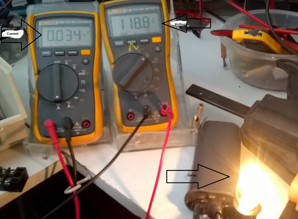
The input decreasing effect was demonstrated in other ZPM replications so obviously something is wrong.
Let's try to find the cause.
First I would simplify the circuit and make it look as closer as I presented it in my demonstrations.
These are the things I would do for the beginning:
- remove that filtering circuit, honestly I can't evaluate how those extra-coils and everything there is affecting the functionality of your device;
- remove that diode, also I can't evaluate how it's affecting the device;
- remove those measurement resistors on input and output, any resistor added to the circuit is seen by ZPM as a load and it's changing its resonance frequency, even connecting the oscilloscope's probes is changing the optimal resonance frequency of my ZPM, when I do that I need to find a new frequency.
The idea is first to make your device reproduce the input decreasing effect without any other things in the circuit. Then once you see the effect you can add other things and see how these things are affecting the device's behavior. It makes no sense to add anything in the circuit now, as long as the input decreasing effect is not present you'll not measure an actual ZPM replica.
I don't know if your DC source is using grounding or not, maybe you should set it to use grounding so we make sure the circuit is as I've shown in my demonstrations. I am aware about the risks when the oscilloscope is using grounding too but for now we don't need the oscilloscope, the goal is to reproduce the input decreasing effect.
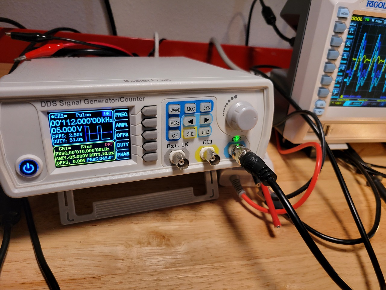
With these things being done I would proceed with a frequency sweep like I've shown here:
Note: the frequency sweep above is made when I have halogen light bulb on ZPM's output, that's more precise as the halogen light bulbs are lighting up instantly, they don't have a delay like the resistive light bulbs.
For making frequency sweep with resistive light bulb this is how I'm doing it:
Why I'm asking you to do a frequency sweep ? Because maybe the frequency you're using is not your device's resonance frequency. With my ZPM if I go below 80 KHz the light bulbs are still shining but the input current is rising close to 1A and even more, which looks like what I see on your source's readings.
If frequency sweep doesn't work as in the videos above then something is wrong in how your ZPM replica is built.
It's hard to see how your coils are built, especially their winding directions because that's important too. And it's hard to follow the winding directions of your coils and how they are connected to each other because your coils are not placed on the core like on my ZPM (I don't know if their positions on the core are important for the device's functionality or not).
Basically when looking at your device from above your coils should have clock-wise winding directions and to should be connected like I've shown in one of my posts here:

I took a photo of my ZPM and noted the clock-wise winding directions of the coils:

As you can see the begining of each coil is starting in clock-wise winding direction but the begining of the bigger coil is connected to the ending of the smaller coil. I also noted the electric polarity of the coils: the end of the bigger coil is always connected to + and the beginning of the smaller coil is always connected to -.
I hope my post helps and could be a beginning in finding the cause why the input decreasing is not present.
Regards,
Fighter
| "If you want to find the secrets of the universe, think in terms of
energy, frequency and
vibration." |
|
|
Nikola Tesla |


.jpg)
.jpg)
.jpg)


