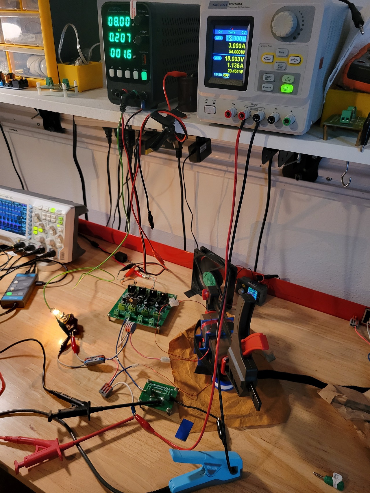
Just received a new MicSig CP1200A 800khz AC/DC current probe, and am very impressed with it. It also speeds up configuring measurements a lot easier.
I dont have a lot of time so I will only post pictures from schematic provided. You will notice my current probe was placed on the positive side of the load. The "negative" side is where I clipped an external ground. If I place the probe after the GND, the ZPM waveform is gone. When I moved probe to other side you can see the waveform.
I also noticed when the PS side is grounded, the input goes down a few hundred mA, though my measurements no matter how much i play with it, using normal probes it shows Math(avg) = -31W, i will post pictures of this when i have time.
I hope I got the following measurements correct, let me know if you see anything that should be altered, any feedback is appreciated.
Schematic: For input and ouput measurement configurations - I am using a Differential Probe for V and Current Probe for I -

Input(Signal generator, scope(detail), scope(waveform):


Ouput(Scope(detailed), Scope(Waveforms):


PS/Setup:

Still a lot to improve, connections, try other loads etc. I've gotten better results but not a lot of time to document as I go, so will try to get my input down farther(which i have at higher frequencies), along with changing other parameters, because there is still a lot of input being used.
I have yet to rewind my smaller coil, so hopefully will have that finished this weekend, hopefully will solve the problem.
Will recalibrate all my equipment and remeasure just in case along with finding better frequencies, just wanted to post some pics with new equipment. And the anomaly where the sine wave appears where gnd is connected, even so on the input i get simalar waveform when PS is grounded.


