BTG research

  • 6.4K Views
  • Last Post 04 May 2024
Vidura posted this 03 August 2022

Hello Friends, I will import this thread; from the backup forum to the public category ,it is dedicated to the BTG devices like the ones shown by Ruslan and Akula. The Goal is to gain knowledge about the involved principals, and hopefully to achieve a working, self-feeding machine. Regarding the tier2 category , I want you to know that I was really tented to post for general public, and certainly the thread will be moved in the replications category when the time is right. But I also know that various persons got in serious troubles , and likely a young man lost his live, because this is the kind of devices produced in series would sensibly cut in the profits of the big energy companies.

We will in a first step go in diakoptik manner thru the different parts of the device and make different kinds of experiments and tests to get basic understanding of how this devices are working, and the interaction of the different parts. Also we will collect information from various sources from the original Builders. I would encourage those of you , who are interested in following or participating in this project, to read the thread about longitudinal waves , as this describes one of the  basic physical principals involved in this device.

The First Part of the device we will cover is the push-pull converter. It's function is pumping charges, an analogy would be the electron-gun in the CRT, it is the source of charges. There is no magic in this part, it is just common EM technology, there are different topologies which could be used, half or full bridge would be suitable. For low frequency devices like the Kapagen also an of the shelf silicone steel transformer could be used. It is important that the output is AC. In the research we will stick to the push-pull topology for the ease of switching the two low side IGBT's. Here some images from testing this stage:

As I have time ,Ill continue to upload content and updates or corrections.

Vidura

Itsu posted this 24 November 2022

I missed the video playlist from Vidura in his 2nd post here: https://www.beyondunity.org/thread/btg-research/?p=&order=all#comment-0012ef69-8926-4d22-80a0-aee6006bc8c2

This playlist to be found here: https://www.youtube.com/playlist?list=PLbhv9RvImM8z4rsOpyOK0vSbgR49WGndK contains a list of videos concerning the BTG including the kacher, push pull, antenna, Grenade etc. with valuable data and measurements.

Modulating (interupting) the kacher also is touched upon and showing the same problems i ran into (not able to get the kacher output sharply pulsed due to the ringing effect).

Thanks,   Itsu

Vidura posted this 24 November 2022

Now I believe that I have already nearly achieved the modulation. Note that in the videos from Ruslan and Akula the modulation is not sharply defined, it looked like the shape of a fish. That is Okay, meanwhile the active portion fits in the corresponding quadrant. But it is very important that the phase is correct, and here it depends some on the design of the lower frequency resonator, it can be used as standing wave or traveling wave resonator and has to be driven accordingly. Regarding the response time of the Kacher-Brovin resonator, it depends a lot on the frequency. With higher frequencies it is much faster, but the drawback is that the potential gets lower cause of less turns. And for a good energy transfer of the scalar waves a few kV are needed...

Vidura

Itsu posted this 24 November 2022

Vidura,

in the videos from Ruslan and Akula and others which show a fish-like signal, i recall those signals were from either the Grenade coil or Inductor coil, not the kacher.
I personally think those fish-like signals shown from the Grenade / Inductor are artifacts from the scopes used, so a trigger problem / setting.

I was able to produce such fish-like signals on the Grenade / Inductor signals by "adjusting" the triggering of the scope, see this video around the 4:15 min time:


Anyway, your modulated Kacher fish-like signals are real, but as you mentioned, the frequency of that modulation (pulse) is around 3kHz, so to low for the needed 24kHz or so we need (push pull).

But those are very interesting vidoes. 

Itsu

Vidura posted this 25 November 2022

Hi All.

As already mentioned the response for modulation of the Kacher-Brovin resonator is in a great extent depending on its resonant frequency and Q factor. The Higher the frequency, the faster is it response. On the other side we also need a sufficient high potential for an efficient scalar wave transmission. I commented on this in the video, there are some effects related to the potential. At a threshold voltage of around 3kv ionisation in the copper conductors occur. Also streamers appear on the hot end on edges and points first And as the conductor length of the resonant coil decrease with higher frequencies, so less turns fits on it. Therefore it will be necessary to overcome this to get sufficient potential. It can be done by increasing the supply voltage of the Kacher-Brovin driver, by reducing the turns on its primary winding, or by reducing the diameter of the secondary (resonator). With respect to the 24khz frequency, in the video I choose this only to show the possibility of modulation at this frequency, but we must understand that it could be any other, but always matching the resonance and quarter of period of the lower frequency resonator of course. In another post I will explain more in detail my hypothesis how this works, the interaction of the different components, and how energy is harnessed from the environment.

Vidura

Itsu posted this 25 November 2022

Thanks Vidura,

very nice demonstration, the interrupted kacher signal can be very powerfull as i understand it.

Can you provide details (diagram) on how you interrupt the Kacher transistor with this little MOSFET you use?

Regards Itsu

Vidura posted this 25 November 2022

@ itsu The Kacher driver is still under development, currently the inductance of the CT has to be adjusted for different frequencies, and I wanted to improve this. But If you wish to experiment with the current version I can share a schematic, when I get back to the pc I will upload it.

Vidura

Vidura posted this 26 November 2022

Hi all , below the schematic of the Kacher driver circuit.

the filterinductors can be around 330uH, it's just the default value in the schematic

Note that the requirements for the layout are the same as described in the bipolar transistor version. Thick  and short traces in the power lines, close to the decoupling capacitors. also the primary has to be a thick conductor or pipe. The inductance of the CT has to be chosen according to the resonator frequency, above 3-4mhz a simple loop of wire around the cold end of the resonator works better, below a ferrite toroid is ok. Accidentally I discovered that by adjusting the gap of a broken toroid the feedback can be calibrated well. Anyway I will try to improove the driver further.

Vidura

Itsu posted this 26 November 2022


Thanks Vidura,

looking nice, i will see if i can put it together and do some tests with it.

Looking forward to your improvements.

Itsu


Aliengrey posted this 27 November 2022

Hi Vidura, Some of your comments are very interesting and explain a lot and i thank you for that.

Any how, i'm interested in the video 7 regarding the biffilar wound layers you refer to, is there any  possibility of  an expilation or diagram on how you wound the coil perhaps a dragram could be possible.

Many thanks Sil 

Vidura posted this 28 November 2022

Replying To: Aliengrey

Thank you for the interest Aliengrey.

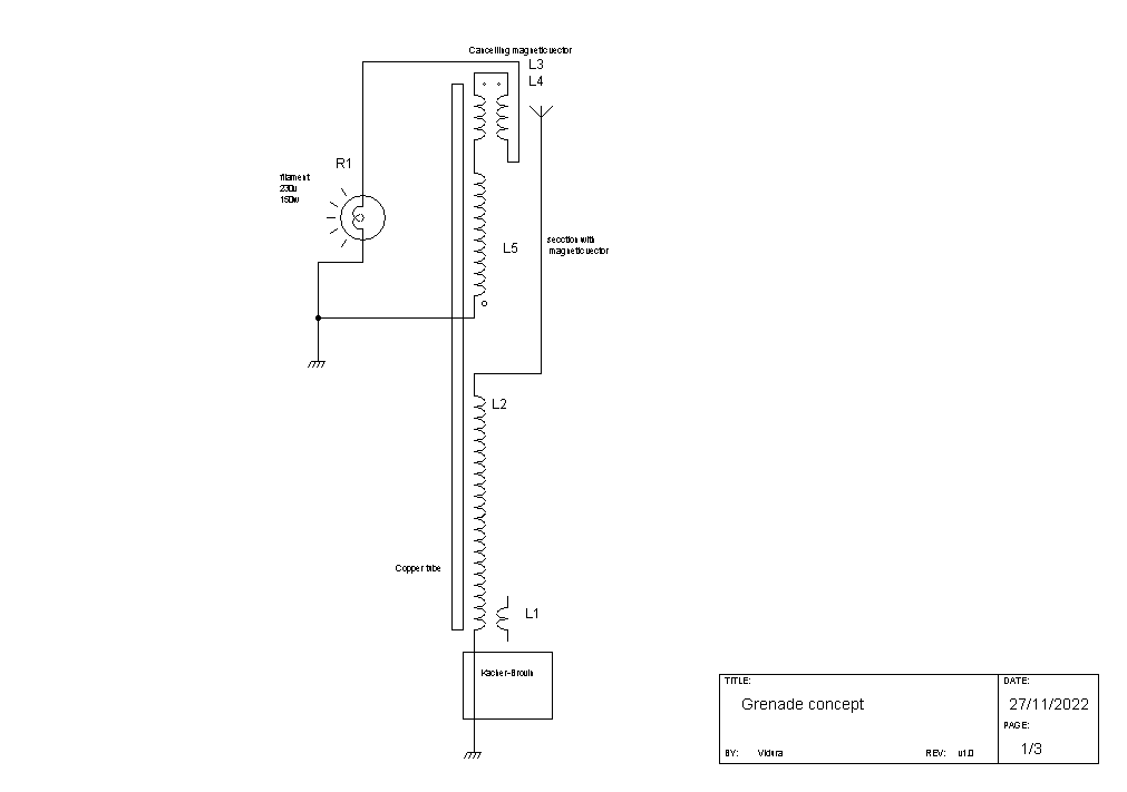
Ok let's go a bit more into details. The concept is basically that we want to transfer scalar waves from the HV-HF source, in our case the Kacher resonator to a secondary coil, for example grenade type. These scalar waves we can produce with a relative low cost of energy, despite of this they carry a huge potential. This waves are of electric nature, and propagate across dielectric mediums(like space or other). When they are intercepted by a conductor, a EMF is induced in the latter. This EMF can or cannot cause a flow of charges in the conductor, depending on its parameters of reactance(XL-XC) and the dV/dT of the incident waves. In the example of video 7 the conductor has two sections, the first(black wire) Is wound as a common spiral, and the second section(blue wire) is bifilar cancelling the magnetic vectors. This is the configuration, which had the best transfer of the incident waves:

When the point of earth ground is changed to the other end of the reception coil, there is barely any output, because the EMF is mostly discharging into the ground. Note the different values of impedance in the two coil sections, the magnetically cancelling part has much less impedance than the common spiral:

In the last test where the antenna is moved to the common spiral section, also the transfer decreased notably, cause of the before mentioned greater impedance:

But this is only one part of the involved concepts….

Vidura

Close