
I transferred my thread on Non Linear Resonance here to BeyondUnity.org
What we consider to be empty space is merely a manifestation of unawakened matter. N.T.
I transferred my thread on Non Linear Resonance here to BeyondUnity.org
What we consider to be empty space is merely a manifestation of unawakened matter. N.T.


Replying To: Jagau
Hello Jagau, I was wondering how a small SG can output more than 2 Watts (had a bad feelin about calculated numbers) . now its clear . Thank you very much ! I dont get a spec sheet from the chinese FG counter but it seems similar to your frontplate (with LCD) but not identical.

(Moved here at Jagau's request)
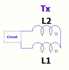
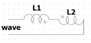
Hi everyone, I've been reading through the threads and there's something I'm a lil confused on I hope could be clarified concerning the construction of the coils. As I understand if we take 2 opposing wound coils and put them in series they can be made to, just from changing the position orientation of 1 coil relative to the other, cancel magnetically and add electrically or cancel electrically and add magnetically.
+B -E (nested):
+E -B:
I see it this way based on the toroidal geometry around the coils and how they would interact.
If this is correct, when do we want the coils to add or cancel one of the respective fields over the other in the pursuit of over-unity?
It's 20 past 3 in the morning for me so I will aim to reply back after I've sleept.
Kinds regards
-R

Hi Jagau, please re-read my question as it is about adding or cancelling a field type, thank you.
Best
-R
Jagau, I am aware of what the purpose of your circuit is for and what it does, I never brought that up nor did I bring up resonance and frequency, those aspects are obvious, let me re-phrase my question:
When do we want to build the coils to cancel magnetically and add electrically?
and
When do we want to build the coils to cancel electrically and add magnetically?
For the schematic here in this thread you said the coils are wound where one is inside the other (nested) and shows the coils to be in series and counter-wound, so L2 and L3 are in magnetic opposition and electrical addition
However on Don Smith Proof of Concept thread the schematic of the coil shows the series nested coils to be wound in the same direction and series conneced at the top, which puts them in magnetic addition and electrical opposition
The coils in this thread and the other thread are opposites field-wise, there's more than 1 type of cancellation hence my question, when do we want the coils to cancel 1 field and add on the other?
Replying To: JenkoRun
When two magnetic fields oppose, they do cancel, yet depending on the construction may bring high potential local capacitive electric fields in regions between the turns. You can only shield or tranform electric potential, or turn into magnetic field, winding doesnt stack or cancel it, other than attaching a equal positive charge to negative(such as two plates) the net charge would be almost 0, but the field terminates on the charges, not cancel. --Rethink, my above reply is incorrect: Faraday's Law states that voltage (electric field) is purely dependent on the speed of the collapse. Because opposing fields accelerate each other's collapse, the time (dt) approaches zero, causing the induced electric field to spike to massive, high-voltage levels.
Quoting:AlteredUnity
Replying To: JenkoRun
When two magnetic fields oppose, they do cancle, yet depending on the construction may bring high potential local capacitive electric fields in regions between the turns. You can only shield or tranform electric potential winding doesnt stack or cancle it.
Hi AlteredUnity, with respect I disagree that winding design cannot cancel (and by extension transform) electric potential, an anti-parallel bifilar winding will put the vectors of both the magnetism and the displacement current generated from the changing potential into opposition with themselves, those coils relate to so called "scalar" waves or Extraluminal as I like to call them.
Floyd Sweet also wrote about the cancelation of both:
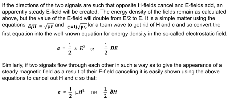
As I understand cancelation of the magnetic component will transform what power it had into electric potential, going by what I've seen in the threads here and off-site, and cancelling the electric potential vectors will transform the power stored in it to another form respectively.
But back to the main matter, even if we ignore subject of electric cancellation I do not understand when it is desired to wind the coil pairs such that they magnetically oppose or add via orientation for series wound pairs, hence I am asking about this and seeking clarification.
Best
-R
I understand, and agree about the scalar fields etc. Was just trying to simply break down the working or counter wound coils you asked about. I strongly believe Ampere, and Tesla's ideas of longitudinal waves.i apologize i didn't put much thought into my reply, as im in the field working atm.

Quoting:Jagau
However, on Don Smith's 'Proof of Concept' thread, the coil diagram shows that the series-nested coils are wound in the same direction and connected in series at their top end, putting them in magnetic addition and electrical opposition.
I see, you're mixing up two threads: NLR and proof of concept, which have no connection to each other.
A tesla coil is not at all what's discussed in my Non-Linear Resonance thread.
There are no extra coils in the NLR thread, only three coils, and there can be more than three. Is that clear enough?
Stop mixing up these two completely different threads.
Jagau
The subject of the extra coils in our private messages are a different topic to what I am asking about here, that question was about open vs closed circuits on the input side, if the input side of the circuit can be an open resonator without closing the loop.
I am not mixing up the threads, an example of a mix up would be trying to copy your circuit on this thread while using the schematics on the concept thread, that's not what I'm doing.
I am referencing the 2 threads because:
1. Both threads cover the topic of over-unity exploration
2. One coil pair magnetically adds, the other magnetically opposes.
As I am lacking in pratical experience I do not know why one would wind them to add or oppose between the 2 example devices, since they are completely opposite in function I referenced both schematics.
I do not know how to ask this question any simpler than I already have; When do we want them to oppose and when do we want them to add?
Regards
-R
JenkoRun, perhaps this is may aid your understanding of the functionality of the two problems you presented:
"When do we want to build the coils to cancel magnetically and add electrically?
and
When do we want to build the coils to cancel electrically and add magnetically?"
The distinction between coils that cancel magnetically and add electrically versus those that cancel electrically and add magnetically comes down to what you are trying to achieve in non-linear or resonant circuit topologies (such as those explored in replication threads for Don Smith, Tesla, or TPU-style devices).
1. When do we want to cancel magnetically and add electrically?
(Example: Nested counter-wound series coils, bifilar non-inductive windings, or bucking coils)
The Setup: Coils are wound in opposite directions (or phased such that their magnetic fluxes oppose each other), but connected in series (or configured) so that their voltages or electric potentials accumulate rather than cancel out.
When We Want This:
To eliminate self-inductance / reactive impedance: When you want a coil or a pair of windings to pass high current or high-frequency pulses without choking the circuit in conventional inductive reactance (e.g., non-inductive resistor/coil configurations).
To create steep gradients / dielectric stress: In many overunity/free-energy research schematics, cancelling the internal magnetic field forces the energy to manifest as an electrostatic or voltage potential rather than a trapped magnetic field.
To prevent core saturation: In transformer or dipole designs where high primary currents are pushed through without wanting to prematurely saturate a magnetic core or create an opposing Lenz's law feedback loop against the driver circuit.
2. When do we want to cancel electrically and add magnetically?
(Example: Aiding coils, Helmholtz-style configurations, or standard tightly-coupled transformer primaries/secondaries)
The Setup: Coils are wound in the same direction and connected to reinforce each other’s magnetic fields. However, depending on how the terminals are tied together (e.g., series-opposing voltage nodes or phase opposition), the terminal voltages can subtract or cancel out externally while the magnetic fluxes combine constructively in the core or space.
When We Want This:
To maximize magnetic flux density: When you need a strong, concentrated magnetic dipole to interact with an ambient magnetic field, a secondary collector, or a spatial dielectric/capacitor plate layout (as emphasized in Don Smith's core concepts where the magnetic field is the primary replicable vehicle).
To isolate electrical feedback (Lenz breaker): By forcing magnetic addition while keeping the electrical loops isolated or phased out, researchers attempt to harvest the magnetic wave propagation without drawing a direct conductive load back onto the primary source.
Summary: The Core Philosophy
The reason you see opposing configurations across different schematics is due to a shift in target medium:
Magnetic Cancellation / Electrical Addition is used when you want to bypass standard inductive choking, collapse traditional back-EMF, and convert spatial setups into high-voltage electrostatic/scalar nodes.
Electrical Cancellation / Magnetic Addition is used when you want to project a pure, unhindered magnetic dipole into space or secondary pickup elements while preventing the electrical load from reflecting back into and killing the primary driver.
((Inception)) "You do not know anything until you have practiced." - Richard Feynman
Now you can experiment with an initial understanding: cause and effect.
Try each configuration and look for the metrics that support the statements above.
Be sure to document your findings. It's a good practice that you may find essential later on.
((Inception)) "You do not know anything until you have practiced." - Richard Feynman

No one online at the moment


