Replication Don Smith's Device No. 9

  • 3.6K Views
  • Last Post 3 weeks ago
ScientificVoyager posted this 10 February 2026

Hi everyone. 

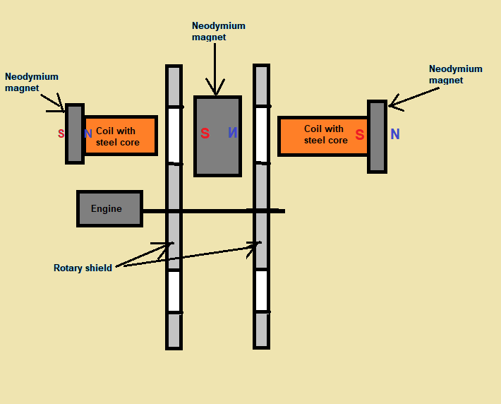
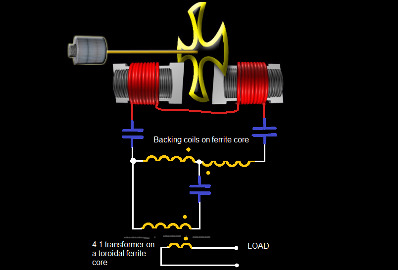
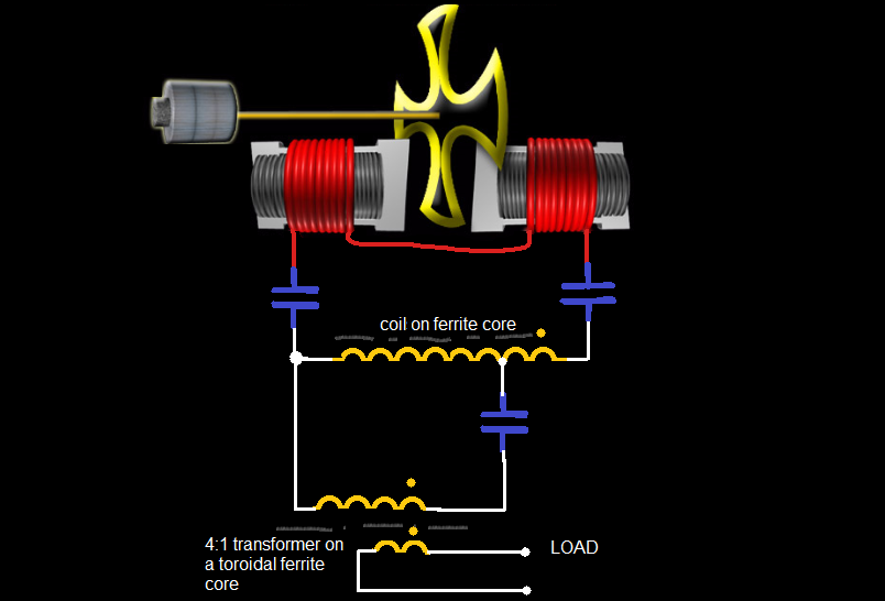
For some time now, I have been interested in Don Smith's replica No. 9. There is not much information about this device, but I decided to make a small replica of it.

Any information about this device would be greatly appreciated.

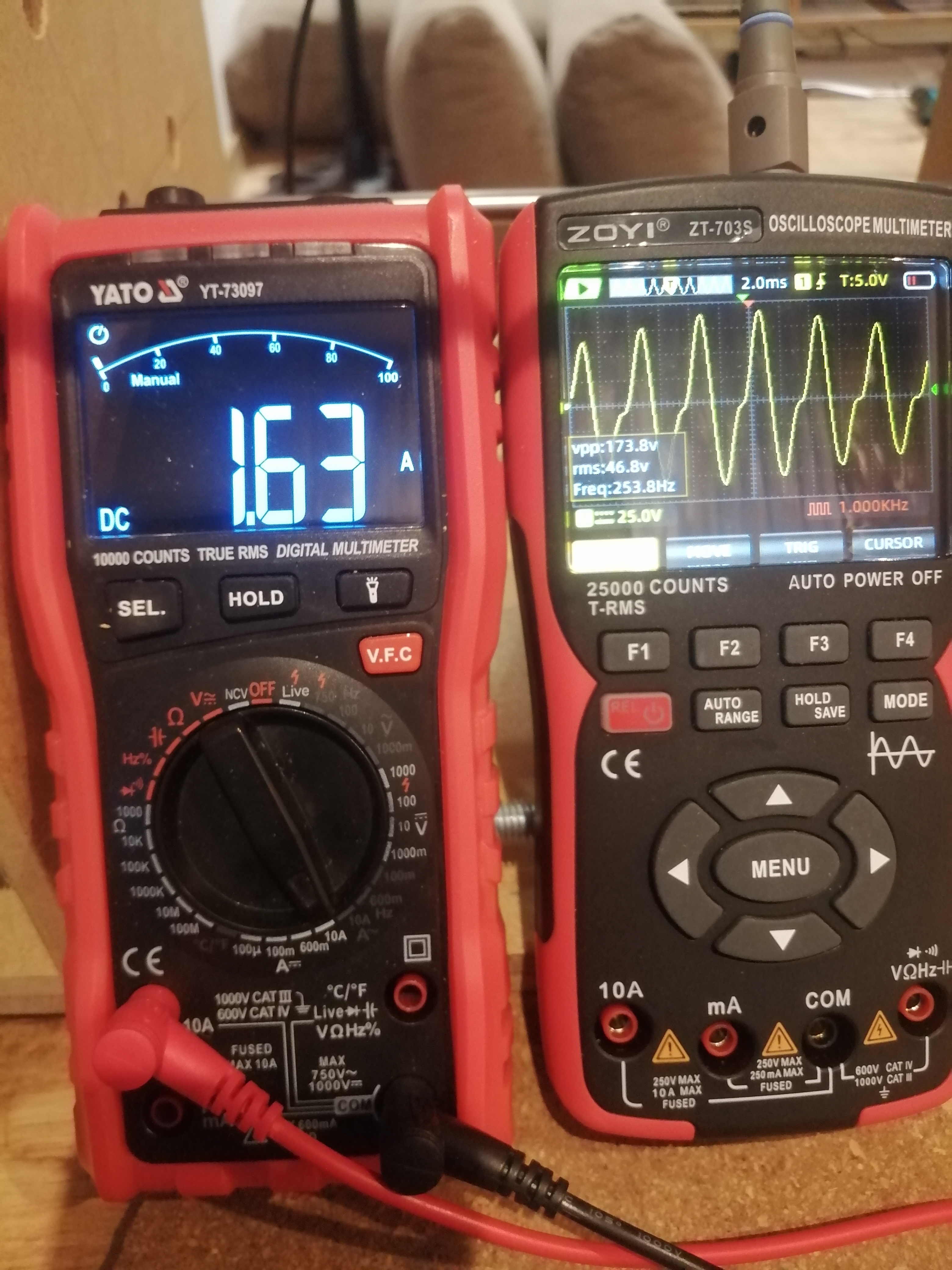
I have conducted some small tests and the results are really interesting because I managed to light a small bulb with two small coils, magnets and a steel disc with holes.

When powering the motor rotating the disc and connecting the load to the coils, the motor driving the steel disc did not feel any resistance while the bulb was lit, with no change in current consumption. That is why I found the effect very interesting and decided to do something more meaningful.

I am in the process of gathering materials and will share my observations with you from time to time.
In general, I have made a wooden structure to put it all together. I commissioned a company that laser cuts such things to make metal discs. The first discs will be made of ordinary steel. I designed the coil spools in FreeCad and they are being printed. Now I am waiting for a delivery of silicon sheet metal to make the coil cores.
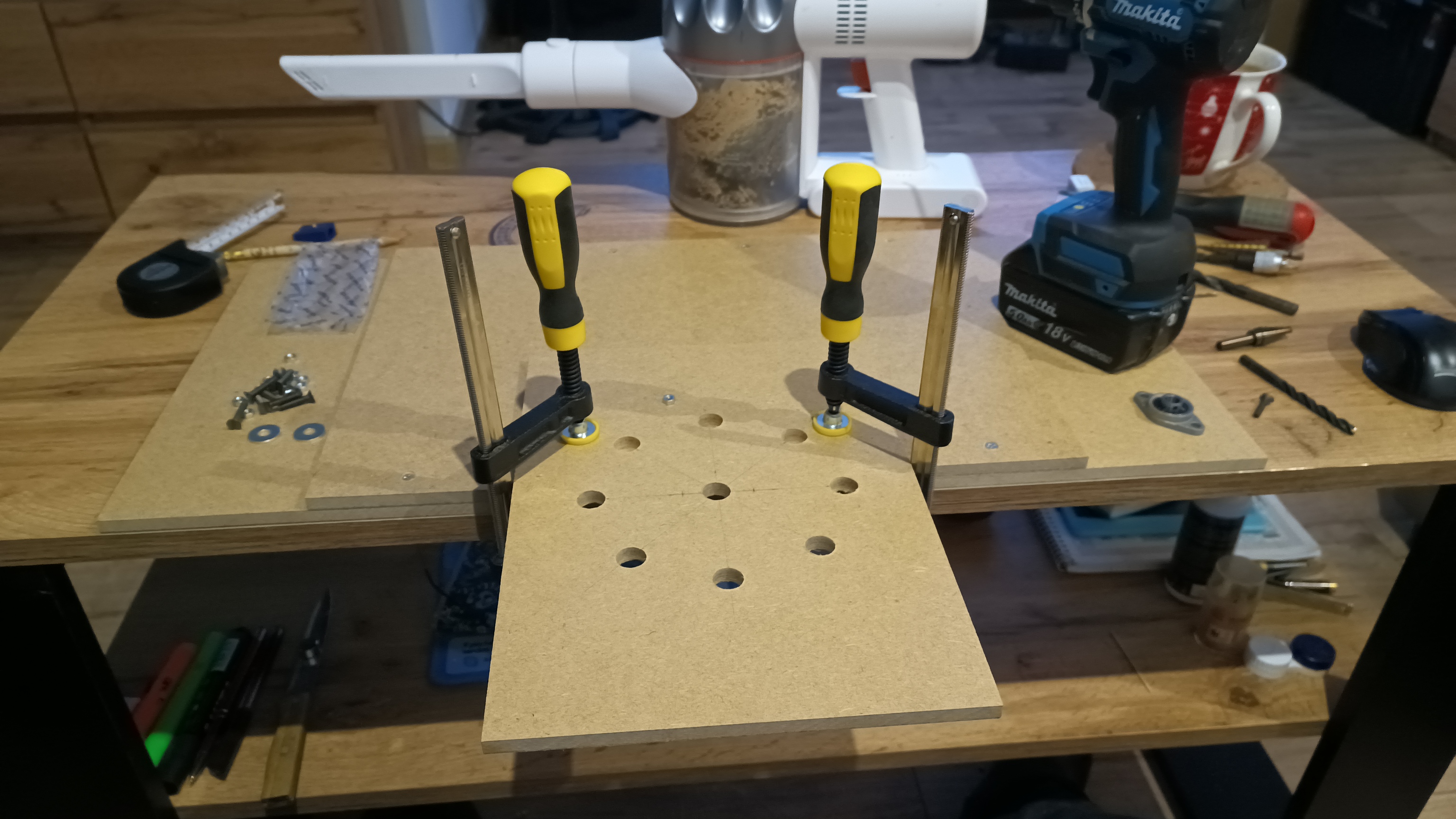
Has anyone attempted to investigate this effect?

The future belongs to those who can imagine it. N.Tesla

andy2 posted this 05 March 2026

No, cores should stay and magnets as they are in your coils. But instead orienting coils with magnets like 
NS - NS
rotate one coil 180degrees

SN - NS

so it should be

SN (coil) - rotating plate - NS (coil)
... so only one rotating plate just between the coils and no more magnets between coils

Like in this diagram (here SN shows only flug going through magnet and coil) :


(here I moved the N and S correctly to the attached magnets)

ScientificVoyager posted this 06 March 2026

@andy2, thanks for giving me something to think about 
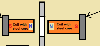
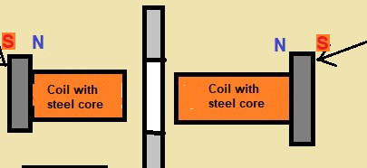
I knew I messed something up in the last test. Thanks to you, everything is starting to look right! You were right, NSNS is the correct form!
I have to change the magnet polarity markings in the drawings again.
Sorry for the confusion
After aligning the magnets correctly, the voltage spiked and the current consumption dropped!
I'll quickly post some photos and a short video.

The photo shows the voltage from two coils connected in series, and the video shows the voltage from one coil.
I definitely need to buy a magnet pole indicator, as it's very easy to make a mistake.
The voltage waveform envelope has improved, and I think it's now a matter of adjusting the distance between the magnets and the coils.
I think DS was right when he said that series LC resonance is necessary in this case. I'll test it, but only with new disc holders, as the current ones vibrate a lot.

The test will be back soon

The future belongs to those who can imagine it. N.Tesla

ScientificVoyager posted this 06 March 2026

Hello.

I ran the test again using this diagram.


The correct magnet position is SNSNSN, and now everything looks good.


The results are surprisingly promising. The next test will be with proper metal disc holders, then I can reduce the gap between the magnets, disc, and coils.

I have to check the oscilloscope probe tomorrow to see if it's okay, because I can't believe that such a high voltage appeared and the capacitor didn't explode, hmm...

The future belongs to those who can imagine it. N.Tesla

ScientificVoyager posted this 07 March 2026

Hello everyone.

Today I checked my oscilloscope probe to see if everything is okay, and it turns out everything is fine.

It turns out that voltage can be generated in two variants: NSNS and NSSN.
It's just a matter of setting the gap between the magnets, coil, and disc properly.
I'm waiting for new disc holders to arrive and then I'll run the tests again.
The conclusion is that this type of generator is definitely worth investigating in more detail.
I'll keep you updated on further progress.

Have a nice day.

The future belongs to those who can imagine it. N.Tesla

Fernando posted this 07 March 2026

Wow, look very promising, how the amps reacts? Still the same? They go lower or higher? Still real power?. Thanks likes always for your neat test.

ScientificVoyager posted this 07 March 2026

Quoting:Fernando

Wow, look very promising, how the amps reacts? Still the same? They go lower or higher? Still real power?. Thanks likes always for your neat test.

Hi Fernando. At this stage, it's hard to say exactly what's happening, because the external magnets are now generally adding power; I'm talking about the SNSNSN magnet system. What's certain is that the power generated in the LC circuit is approximately 39 watts. The capacitor in the resonant circuit is a non-polarized type with values ​​of 6.8uF/50V, and it gets warm as the rms voltage reaches about 62V.


The oscilloscope shows 58V RMS (confirmed with a multimeter), and the current in the LC circuit is approximately 0.67A.

The drive circuit itself draws about 3.3A, without the LC circuit engaged. Adding a capacitor increases the motor's draw by about 1A, and 39 watts are generated in the LC circuit. This means that the current consumption in the drive circuit requires about 12 watts (12V x 1A) to produce 39 watts in the LC circuit.
It's clear that now we need to somehow extract power from the resonant circuit through impedance matching.


PS.

I achieve the highest efficiency by matching the RPM to the LC circuit's resonant frequency. Watch the video (I'll post it soon) as I try to match the RPM to the LC resonance, and see how it affects the current and voltage in the circuit.

I managed to increase the power in the LC circuit to 49 watts.

The measured voltage in the circuit is:
- Idle without LC circuit: 14V x 2.95A = 41.3W
- Operation with LC load: 14V x 3.74A = 52.36W
- Power measurements in the LC circuit: 62VRMS x 0.79A = 48.98W

Summary:
52.36W - 41.3W = 11.06W (this is the power required to produce 49W in the LC circuit).

DS said in his lectures that we cannot obtain power directly from the generator output, we need to transmit energy and impedance match it to the load.

Now we need to transfer this power from the LC circuit to the load via impedance matching, and this is where I need help.


Any suggestions are welcome.

The future belongs to those who can imagine it. N.Tesla

ScientificVoyager posted this 08 March 2026

I'm wondering how to properly convert power from an LC circuit to a load.

or this version


There are so many wonderful and talented people here, so I'd like some advice on how to properly transfer this power.

The future belongs to those who can imagine it. N.Tesla

baerndorfer posted this 08 March 2026

to extract power from a resonating system i always use a 'diode-plug'.


additional information about the diode-plug

i am sure it will work for you, as it works for me

regards

B

ScientificVoyager posted this 08 March 2026

Hi baerndorfer. Thanks for the link.

Would you suggest this combination?

or such a configuration?


The future belongs to those who can imagine it. N.Tesla

Jagau posted this 08 March 2026

Bearndorfer is right, and it works well that way.
Another circuit you can try is an open circuit connected with a single wire plugged into the center of the two red coils. That's where you'll get the most voltage with the diode connected to a single wire at that point.

Jagau

What we consider to be empty space is merely a manifestation of unawakened matter. N.T.

Close