Is there energy Gains in Adam’s patent, the great question.
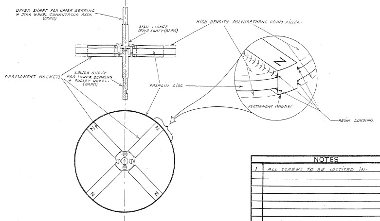
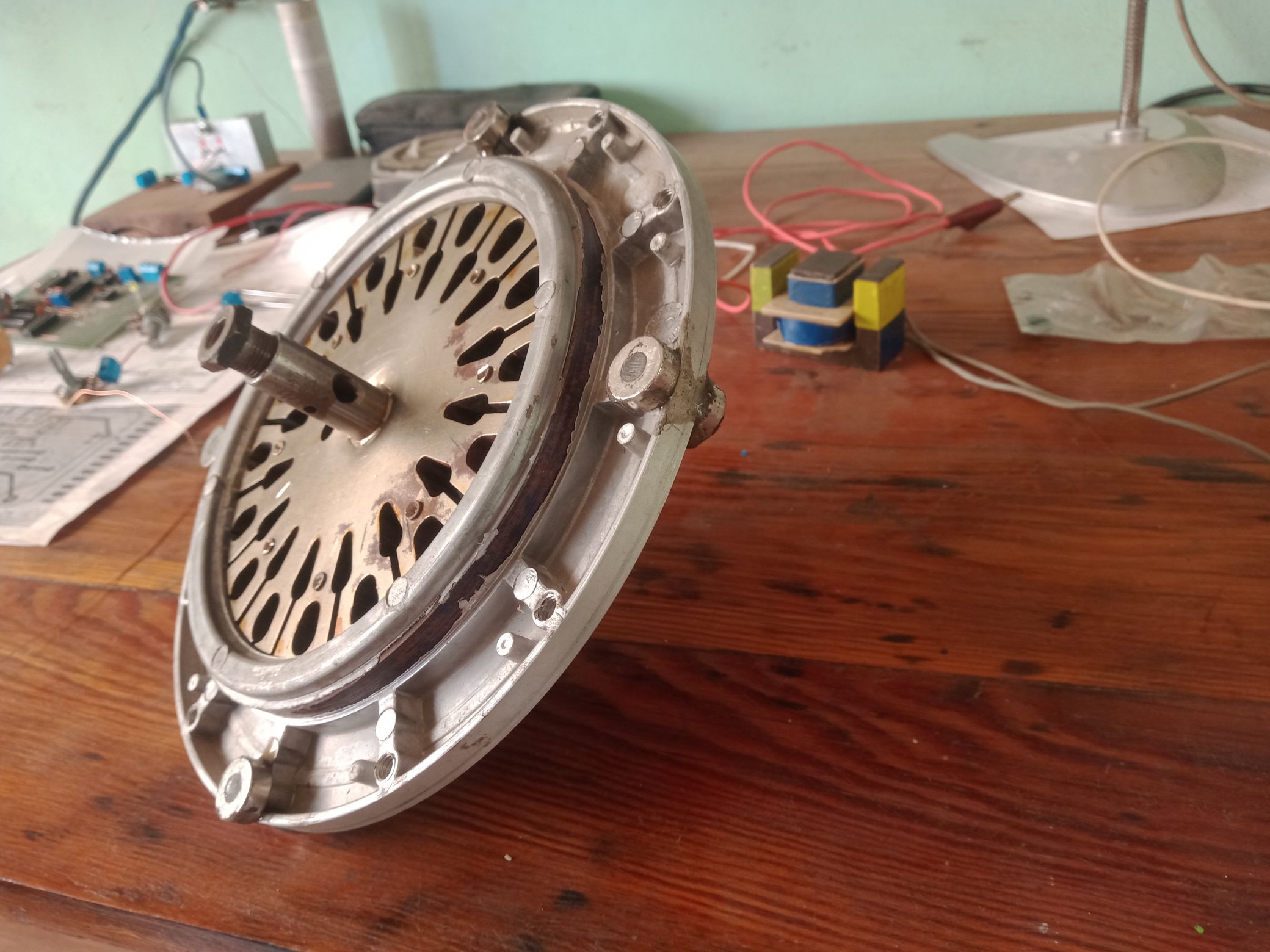
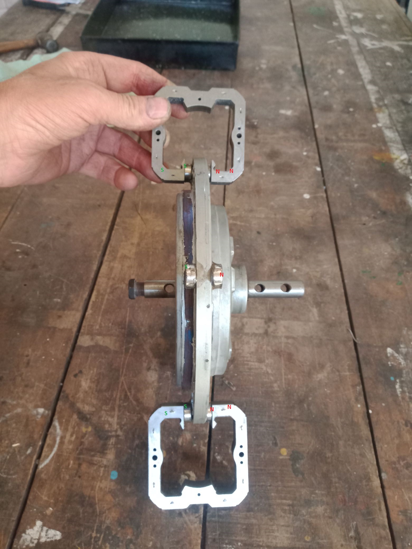
I built an Adams motor using a computer HDD to simplify the assembly of the bearings and with the installation of six permanent neodymium magnets on the rotor. This is Robert Adams’ first advice in order to understand the operation and then build a bigger one.
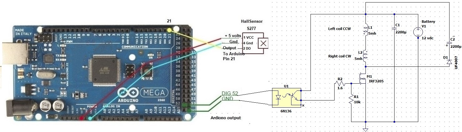
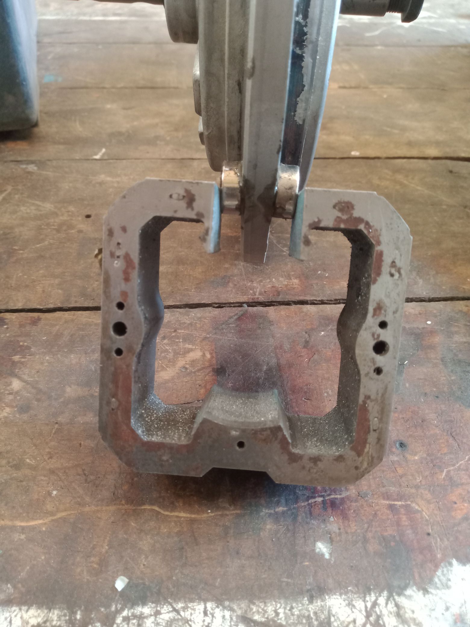
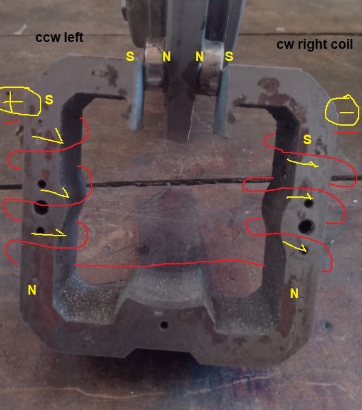
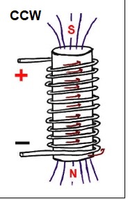
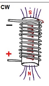
In order to study the behavior of the motor I use two 5 milli-henry coils on each side at 180 degrees from each other with the left side winding CCW and the right CW, the coils are connected in series.
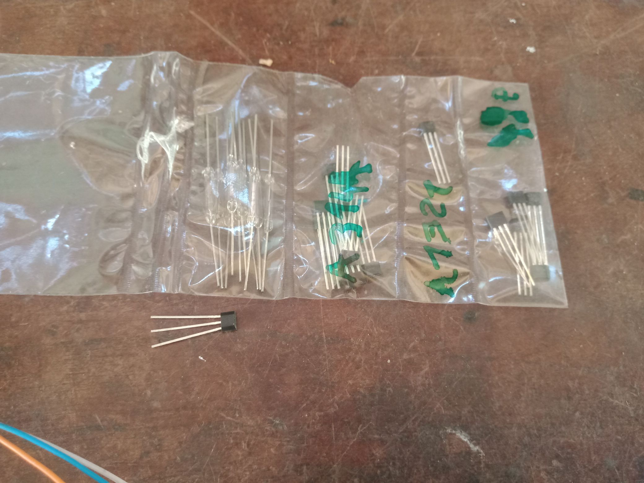
The control system will be done with an Arduino mega 2560 using a hall effect sensor S277 for detecting the position of the rotor relative to the magnets. On the hall sensor S277 that I recovered from a computer fan, only the DO output (pin 2) will be used to give the interrupt detection instruction (it is in the Arduino program) in order to activate a 6N136 optocoupler to give a pulse on the Gate of the Nmos IRF3205 which will activate the two coils in series of the motor as declared by the inventor Mr. Robert Adams.
Photo to come
Jagau
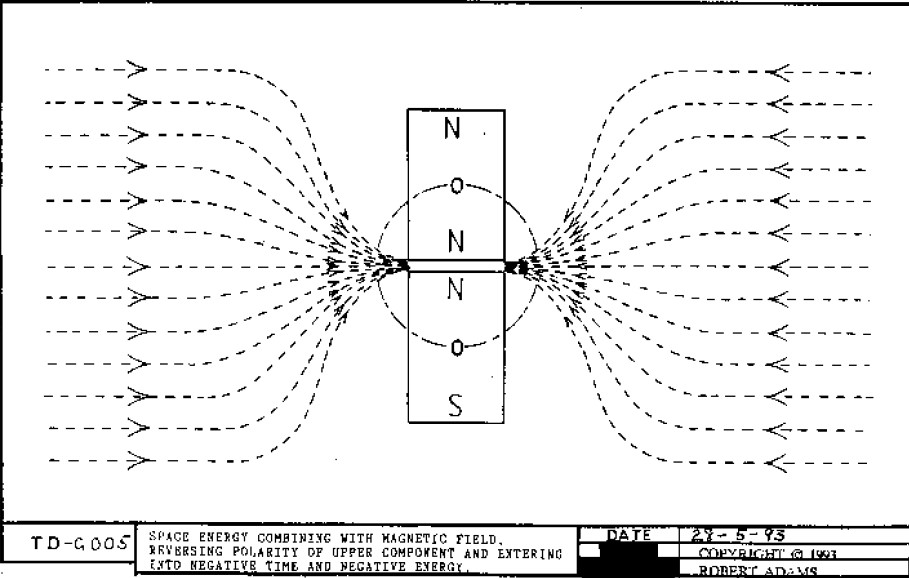
What we consider to be empty space is merely a manifestation of unawakened matter. N.T.