Energy Gains in Adam's patent.

  • 5K Views
  • Last Post 2 weeks ago
Jagau posted this 07 September 2024

Is there energy Gains in Adam’s patent, the great question.


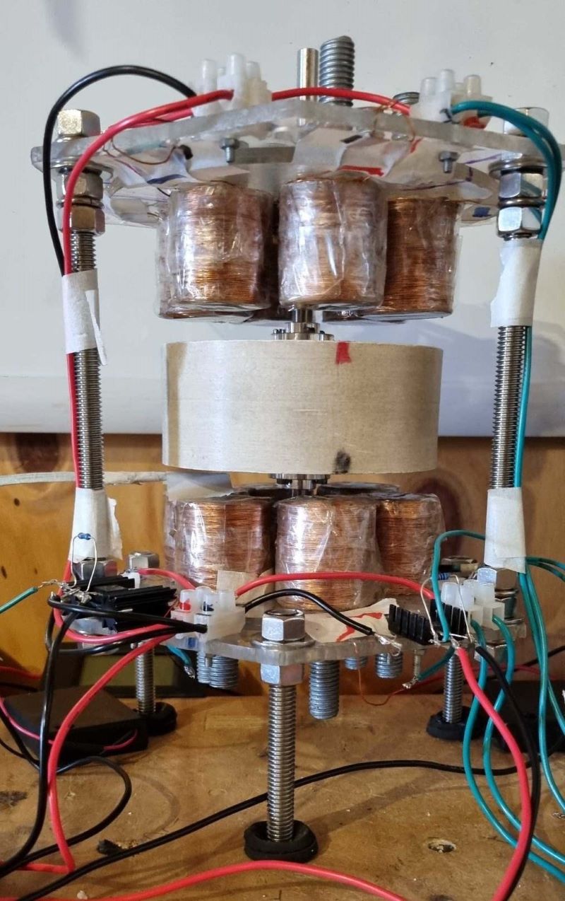
I built an Adams motor using a computer HDD to simplify the assembly of the bearings and with the installation of six permanent neodymium magnets on the rotor. This is Robert Adams’ first advice in order to understand the operation and then build a bigger one.

In order to study the behavior of the motor I use two 5 milli-henry coils on each side at 180 degrees from each other with the left side winding CCW and the right CW, the coils are connected in series.

The control system will be done with an Arduino mega 2560 using a hall effect sensor S277 for detecting the position of the rotor relative to the magnets. On the hall sensor S277 that I recovered from a computer fan, only the DO output (pin 2) will be used to give the interrupt detection instruction (it is in the Arduino program) in order to activate a 6N136  optocoupler to give a pulse on the Gate of the Nmos IRF3205 which will activate the two coils in series of the motor as declared by the inventor Mr. Robert Adams.


Photo to come

Jagau

Jagau posted this 29 November 2024

update

The new tests lead me to believe that the amps / turns are very important in this type of motors. I reached a quarter of the required power i.e. 1/4 of a watt for the same returns as on the first video. So the MMF A/T is important to considered.

Jagau

Unimmortal posted this 12 February 2025

Here are a couple of links I wanted to share. This talks directly to the bias that can be applied to the horizontal rotating field, which may get some of you thinking about how this applies to the Adams generator.


Jagau posted this 12 February 2025

HI

Bruce de Palma who is the inventor of the Nmachine speaks a bit like you.
Read this it will interest you more precisely on the bias applied to rotating magnets.

https://depalma.pairsite.com/


Jagau

  • Liked by
  • Inception
Unimmortal posted this 13 February 2025

Yes, I've investigated nearly all of the well known FE devices before picking the Adams to work with. There are a lot of similarities across all of them and I believe I've found the last piece to make mine work.

The rotating field creates two vortexes (either side of the rotor) that also rotate and can be locked / biased - as shown in those videos. The field forms at the bloch wall - which is etheric. What Adams has very cleverly done is wind his pulse coils to not only pulse, but to bias both vortexes of the rotating field by creating opposite fields to keep it busy by way of counterwinding pulse coils.

Why bias the rotating field? When the vortexes are busy reconciling what the pulse coil is doing to the overall spinning field, the generator coils are now working with magnets that are part of a larger system, and that larger system is now inherently missing a pole, giving us the 'like poles attracting' phenomena.

This allows the generator pulse to pull the opposite field from the magnet as both ends have both poles (Howard Johnson wrote an excellent book on magnets), as there is no opposite force to equalise this - because it has been biased (or distracted) elsewhere by the pulse coils. With these conditions in place, the generator coils are now pulling aether directly without being impeded by equilibric forces.

You might be asking why I haven't a working example yet - it's because my design is axial based and not radial, so chasing and biasing that rotating field is a little more challenging. With radial, it's already quite literally spinning across your coils by default.

It's a bit to get your head around, so get your pulse motor, get rid of all but one coil and gently play with magnets around the spinning rotor. 

Jagau posted this 13 February 2025

HI Olli and unimmortal

The 3 conditions for the success of the Adams engine according to me:

The first condition to obtain a high efficiency in the Adams engine is that the engine uses the least possible energy from the source just enough to overcome the rotational friction.
The second is to reuse the energy of the flyback EMF during the collapse of the magnetic field of the coils and by a set of diodes and capacitors to reinject it into the source.
The third is the commutation, in the precision of this one and especially what is the most important the type of commutation which must be as fast as possible.

As for the first condition I have almost reached it, the consumption is extremely small. For the second I built an electronic circuit that transfers this free energy with a precise adjustment of the frequency and the duty cycle and in the right period of time.

For the third it is the most complex and it is currently being tested. This is the one that will allow to have beyond unity, which is obtained by an etheric condition of switching.

Jagau

Unimmortal posted this 20 February 2025

Here is my little device I'm now calling EMMA

Most of the journey has been documented over at mooker.com, but here is the latest variant I'm working with.

Configured as described above I'm around 70ma short of parity (330mA V 400mA) when outright shorting the generator coils. Switching is a little tricky as the native wound coils do their thing fine - consistently able to get 1-1.4A. However the re-gauged coils have a different switching characteristic that may need to be dealt with individually - having said that, getting 1A out of them individually wasn't too hard. 

There's a bit of air-gap here, but that's because I'm using half of my generator coils as pulse coils (this is the mini version) - and pulse doesn't need to be quite so close. Having said that, the pulse coils are working together generating as well but I haven't put any focus on input conservation or reclamation yet.

Pulse and generator coils are approx 37mmx37mm, 20mm core, approx 1200 turns of AWG24, and in a set of 3 have 25ohm resistance - about perfect for the 18-36V that I drive it with. Magnet stack is 20x20mm+5x10mm+20x20mm to make it 45x20mm, N40, 3 to a rotor.

Other iterations of this motor/generator have given me upwards of 140-150VAC, so hopefully now that I've got all the pieces I can get some real power out.


Unimmortal posted this 21 February 2025

@Jagau - absolutely agree on all points. I've now found my pulse width is now critical to getting the most out of the generator coils Quick update on what EMMA is currently achieving: Input: 36V@400mA, Output: Shorted Input: 36V@210mA, Output: Open, 55VAC Input: 36V@320mA, Output: Switched, 1.5A

Jagau posted this 21 February 2025

Hello unimmortal

You are a serious builder, you have done a great demonstration.

Commutation is the brain of the Adams motor, I think you have commutation with relays? Adams preferred mechanical switching.


Another good serious builder here from Atti who is member here:

With some similarities to yours


You will find his thread here

https://www.beyondunity.org/thread/permanent-magnet-motors-and-their-similarities/


Jagau

Jagau posted this 26 February 2025

update

I rebuilt the Adams motor with 4 standard ferrite magnets lengthwise and with similar results as first one with neo magnets. The neodymium magnets are not necessary, the standard ferrite magnets work just as well. And even the consumption is lower.

Other tests in progress, the Adams motor is really a quantum motor that uses the energy of the universe to achieve performances beyond unity.

Jagau

Jagau posted this 28 February 2025

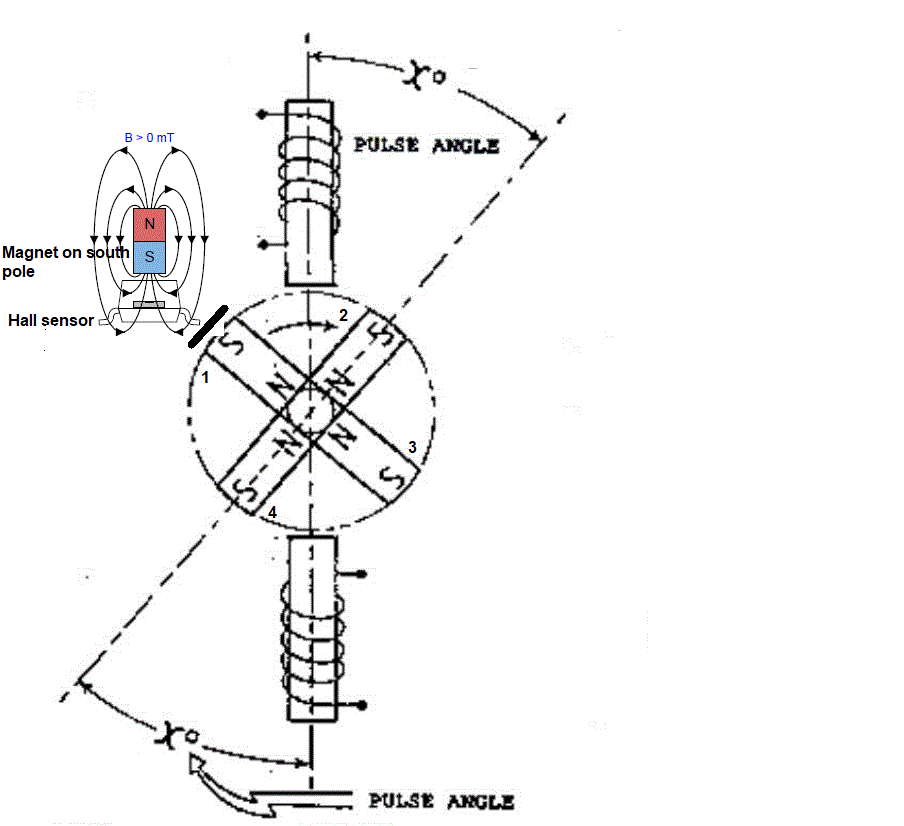
In Adams' PEMG (Pulsed Electric Motor Generator), the position of the position sensor of the rotor magnet no. 1 that rotates to the right is critical and accurately determines the pulse angle. You can see in the attached drawing the position of the hall sensor facing magnet 1.

As magnet 1 is naturally attracted to the stator iron and when it passes it until the moment of the pulse, this natural attraction is approximately equal to the drag produced by the magnet on the stator iron and it is the timing of the pulse that determines the efficiency of the PEMG on magnet no. 2 that I made with Arduino mega 2560.

JL Naudin had published under GNU form a software that he used for the timing of this very important pulse. I imported and modified it according to my beginner knowledge in ARDUINO and it works wonderfully well. All credit for this program therefore goes to JL Naudin. I just modified it for my needs.

The next post will be on the Arduino program.

Here is JLN's Arduino program in attached file.

Jagau

Attached Files

Close