Spatial Energy Coherence circuit

  • 12K Views
  • Last Post 2 days ago
  • Topic Is Solved
Jagau posted this 14 February 2023

Hi all

This thread will be dedicated to an inventor who left us a lot of information on "Spatial Energy Coherence" commonly called "SEC"

This circuit connects to the sea of energy that surrounds us by opening a door with it. Building different circuits will teach us more and how to do it.
Thank you Dr. Ronald Stiffler.
Jagau

Jagau posted this 10 April 2025

If you work well with Dr. Stiffler's SEC circuits, you can be sure of achieving Beyond Unity.

I don't know if any researchers have continued with this type of circuit, but as Dr. Stiffler and several of his videos on YouTube have demonstrated, we're getting there.
The interest of research sites around the world seems to have waned a bit these days, but I'll soon be posting a video proof of what Dr. Stiffler has proven when time permits.

The "primary" and "secondary" of Dr Stiffler Transformers are not magnetic inductors. They are resistive capacitors. Coil-shaped capacitors! DrStiffler Transformer action is electrostatic induction.

Same construction used with N.Tesla transformer.


Jagau

Jagau posted this 16 April 2025

There's a way to modify Dr. Stifler's oscillator to produce an AC pulse train.
The result on output is impressive.

Here we can see the 7.54 megahertz pulses


and here the pulse of 7.54 mhzof  train at 540kHz

more images to come

Jagau

Jagau posted this 24 April 2025

The ether pulsates and moves in the form of vortices.
Dr. Stiffler's SEC output confirms this.

Jagau

  • Liked by
  • Fighter
  • Inception
Jagau posted this 30 April 2025

SEC Exciters do Not create energy; they do not amplify energy either. Think of an  Exciter as causing a door to open slightly and allowing a natural energy to leak through into the circuit.

Cohered Energy Coefficient Vs over Unity, Explained by Dr. Ronald Stiffler

Let me one more time try to present a description of what CEC or Cohered Energy Coefficient is. CEC is not OU or Free Energy, it is very similar to COP yet COP is not directly applied to electronics (or should not be).

Think of a vast lake on which multiple speed boats are running back and forth, the lake is the Energy Lattice, and these boats are all causing waves over the lake, multiple oscillations in the lattice, and you focus on a certain spot and watch the effect of the mixing of the waves, some additive and some subtractive. 

Now the additive waves can be a combination of many boats and not a direct result of just one boat although possible under certain conditions the energy if you measure it is the sum or difference of all wave energy present in your observation and can be found to be greater than from anyone boat, this is CEC.

Now if you want to average the energy over time from all boats you will still get a coherence >1 above a single boat the only one you are concerned with, Exciter, but the CEC of the whole lattice is =1.

If it were not equal to one then we would have a negative energy universe.

Jagau

  • Liked by
  • Fighter
  • Inception
Jagau posted this 01 May 2025

An excellent article by Nikolay ZAEV on energy transfer using, 

Stanislas Avramenko's diode plug.

https://electro-en.tomathouse.com/main/praktika/21-peredacha-jelektrojenergii-po-odnomu.html

Jagau

Jagau posted this 16 May 2025

Some words of Ron Stiffler:

SEC stands for 'Spatial Energy Coherence' and is a theory I developed about how my exciters are capable of cohering energy from what I describe as the spatial energy lattice.

When one is able to coherent the energy of the lattice, and within the framework of proper circuit design , one can see a coherent energy coefficient (CEC) > 1.

SEC is not the circuit; exciters are the circuits. Exciters do not produce beat frequencies below 4 MHz under any (properly tuned) conditions.

Everything what Doc Stiffler said is true and verified. With a properly tuned 15-3 SEC, you can easily exceed 1 and I easily surpassed it much more than 1


Jagau

  • Liked by
  • Fighter
  • Inception
Jagau posted this 28 May 2025

I repeated the following experiment with the anti-parasite plate. The results when coherence is achieved are more than convincing; I easily obtain a CEC greater than 1.

All while following the measurement method recommended by Dr. Stiffler.

The position of the coils is very important, they are all at 90 degrees to each other.
Demo to come in the next post.
Jagau

Jagau posted this 29 May 2025

The following photo shows the replication of the SEC 15-3 with a ground suppression system, mounted on a copper foil.
I obtain 122.9 volts at the output of the Avramenko plug and a power consumption of 0.3 watts on a 12-volt battery.
The operating frequency of the exciter is 12.26 megahertz, as seen on the SA.


When the vacuum energy network is energy coherent, 18 LEDs can be lit very brightly, as you can see in the following photo.

At coherence, the consumption of the LEDs does not change the primary load, which is still at 0.3 watts input, producing more than 1 watt of light at the output.

Next post on power analysis using Dr. Stiffler's formulas.

Jagau

Jagau posted this 30 May 2025

To take good measurements on this type of circuit some filters like this must be built. Remerber we work at megahertz range.

Measurement Circuits
First and foremost in working with SEC Exciters is the required isolation of the Exciter from its power source, regardless of the type of the source which could be one or more of; a line powered power supply, battery or solar cell.

To accomplish this many different filters were tried that ranged from simple to complex with component costs to match and one general design was found that worked best.The filter found to be most effective at providing the required decoupling was found to be a relatively simple and inexpensive multi-stage filter built from readily available RF Ferrite Beads and Ceramic Capacitors. The circuit diagram for the power supply filter is shown here.

Parts List.
C1 1uF 100V, Al Radial +/-20%, Part# 158491 [4]
C2-C6 0.01uF @ 1kv Ceramic [4]
B1-B8 Ferrite Beads on leads of Z=86 ohms @ 10MHz [5]

The filter can be constructed on available prototyping circuit boards available from most electronics parts suppliers. Whatever construction method is used must take into consideration that the filter is designed to remove wideband RF energy and as a result must be constructed in a straightforward and acceptable layout.

more to come

Jagau

Jagau posted this 01 June 2025

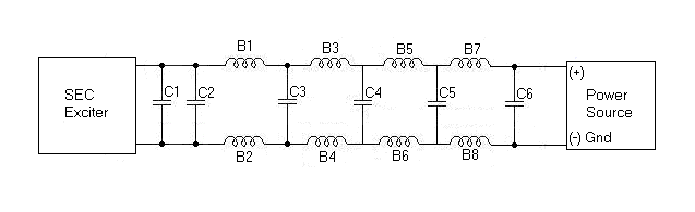
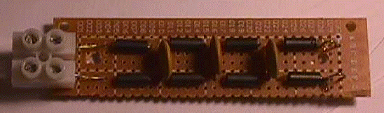
In order to take good measurements without interference the following filter must be made for measurement through a 1 ohm resistor.

The oscilloscope with its high impedance input gives us a very accurate average DC reading.

Parts List.
C1 1uF 100V, Al Radial +/-20%, Part# 158491 
C1-C4 0.01uF @ 1kv Ceramic 
B1-B10 Ferrite Beads on leads of Z=86 ohms @ 10MHz  and for measurement one 1 ohm carbon resistor.

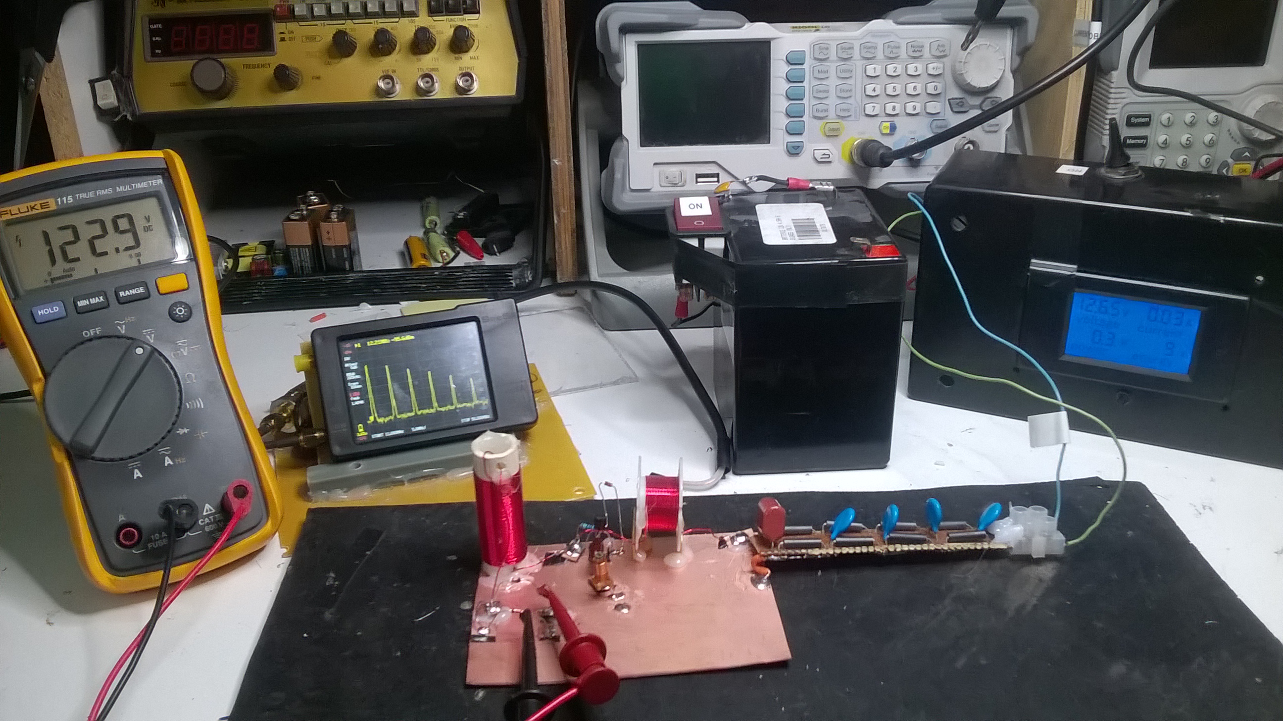
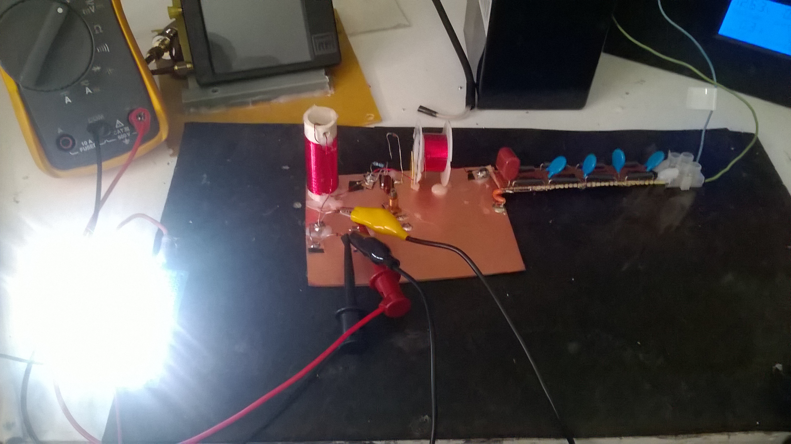
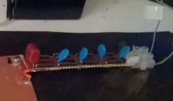
You can see the string of 18 LEDs after the AV plug, followed by the filter, and finally the oscilloscope. This type of measurement provides great precision.

The current in the series LED string is derived from the voltage drop across the 1-ohm resistor. Each 0.001-volt drop across the 1-ohm resistor is equal to 0.001mA of current; therefore if the reading is 0.024 volts, the current is 24mA.


You can calculate the power of the LED string by knowing the forward voltage drop of the LED’s being used and multiply the number of LED’s times the voltage drop across one LED, times the current from your reading across the sample resistor.

Here is Dr Stiffler formula:

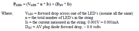
This formula can be used for most of your projects with LED strings.

 Jagau

Close